
01 · Cockpit Control Architecture
Cockpit Control Architecture: Panels 225VM, 211VM, 255VM & 222VM
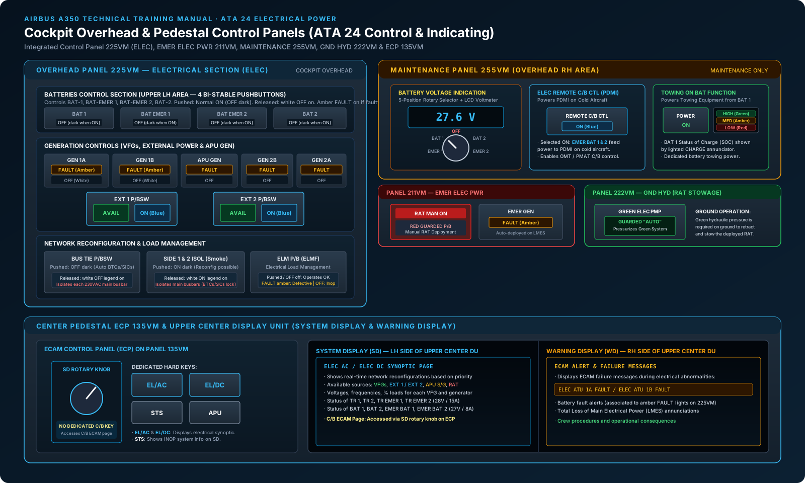
The primary human-machine interface for the Airbus A350 Electrical Power System is distributed across four distinct overhead panels and two maintenance reset panels, as specified in the maintenance course syllabus. System designers consolidated operational controls on the forward overhead while isolating emergency and ground maintenance functions into segregated structural panels:
1. Overhead Panel 225VM (Electrical Section — ELEC)
Positioned in the central overhead console, panel 225VM contains all primary controls for standard flight operations. The panel is logically divided into three primary functional zones:
- Battery Control Section (Upper LH Area): Four identical bi-stable pushbuttons control the connection of the aircraft batteries:
BAT 1,BAT EMER 1,BAT EMER 2, andBAT 2. In normal operation, each pushbutton is pressed in (ON position), with the whiteOFFlegend extinguished. When released, the whiteOFFlegend illuminates. If an internal battery or charger fault occurs, an amberFAULTlegend illuminates, accompanied by an ECAM alert message on the Warning Display (WD). - Generation & External Power Section: Controls for the four engine-driven Variable Frequency Generators (
GEN 1A,GEN 1B,GEN 2B,GEN 2A) and theAPU GEN(the 230 VAC starter/generator managed under ATA 49). Each generator pushbutton presents a split-legend display: an amberFAULTlamp indicating generator trip or protective opening, and a whiteOFFlegend indicating manual disconnection. Flanking the center are theEXT 1andEXT 2pushbutton switches, featuring a greenAVAILlegend (GPU connected with nominal frequency and voltage) and a blueONlegend (external power contactor closed to energize the aircraft network). - Network Reconfiguration & Load Management:
BUS TIE P/BSW:Controls automatic cross-tie reconfiguration. When pushed (normal), theOFFlegend is dark, and the Electrical System Controller automatically manages Bus Tie Contactors (BTCs). When released, the whiteOFFlegend illuminates, opening the tie contactors to completely isolate each 230 VAC main busbar.SIDE 1 & 2 ISOL P/BSW:Dedicated to the electrical smoke isolation procedure. When pushed (normal), theONlegend is dark and normal tie reconfiguration is permitted. When released during smoke drills, the whiteONlegend illuminates, opening tie contactors to isolate side 1 from side 2 and prevent electrical smoke propagation.ELM P/B:Controls the Electrical Load Management Function (ELMF). When pushed (normal), theOFFlegend is dark and the ELMF automatically manages load shedding. If an internal fault occurs, an amberFAULTilluminates; releasing the button disables automatic load management, illuminating whiteOFF.
2. Overhead Panel 211VM (Emergency Electrical Power — EMER ELEC PWR)
Panel 211VM houses the emergency generation controls. Its central feature is the red guarded RAT MAN ON pushbutton switch. While the Ram Air Turbine deploys automatically in flight upon total Loss of Main Electrical Power (LMES), lifting the guard and pressing RAT MAN ON forces immediate pyrotechnic/hydraulic deployment. An adjacent EMER GEN FAULT amber annunciator illuminates if the emergency generator fails to come on line or experiences out-of-tolerance voltage/frequency parameters.
3. Maintenance Overhead Panel 255VM
Located in the right-hand overhead console, panel 255VM is reserved for ground testing and maintenance procedures. It contains three critical specialized sub-systems:
- Battery Voltage Indication: A five-position rotary selector switch (
OFF,BAT 1,EMER 1,BAT 2,EMER 2) connected directly to a dedicated digital LCD voltmeter, allowing line maintenance personnel to measure open-circuit and loaded battery terminal voltages directly from the cockpit without energizing the aircraft electrical network. - ELEC REMOTE C/B CTL Pushbutton Switch: Powers the Power Distribution Maintenance Interface (PDMI) on a completely cold aircraft using emergency batteries, illuminating a blue
ONlegend. - Towing on Battery Power: A dedicated
POWERpushbutton switch and a three-level verticalCHARGEannunciator (HIGH green, MED amber, LOW red) that powers ground towing intercoms and external lights from Battery 1.
4. Panel 222VM (Ground Hydraulic — GND HYD) & Reset Panels
Overhead panel 222VM contains the GREEN ELEC PUMP guarded "AUTO" pushbutton switch. Because the Ram Air Turbine actuator utilizes Green hydraulic system pressure for on-ground retraction, panel 222VM provides the necessary control to pressurize the Green hydraulic circuit during ground maintenance. Additionally, maintenance reset panels 213VM and 232VM house the manual RESET pushbuttons for Transformer Rectifier 1 (TR 1) and Transformer Rectifier 2 (TR 2).
02 · Electronic Centralized Aircraft Monitoring
ECAM Indicating: ECP 135VM, SD Rotary Selector & Upper Center DU
Electrical system status, voltages, currents, and component failure alerts are processed by the Flight Warning System (FWS) and Control and Display System (CDS) and presented on the Upper Center Display Unit (DU-UPPER, CENTER). The layout and control methodology introduce a fundamental operational rule unique to the A350:
Vital Engineering Distinction: No Dedicated C/B Key on ECP 135VM
Unlike earlier Airbus families (A320, A330/A340) where a dedicated C/B key exists on the ECAM Control Panel, the Airbus A350 ECP 135VM does NOT feature a dedicated C/B pushbutton key.
To view the Circuit Breaker ECAM synoptic page on the System Display (SD), the flight crew or maintenance technician must rotate the SD rotary selector knob positioned on the left-hand side of the ECP. Turning this rotary knob cycles through the secondary system display pages until the C/B page is displayed on the LH half of the Upper Center DU.
Display Partitioning on the Upper Center DU
The Upper Center Display Unit is optically partitioned into two distinct vertical display domains:
- Left-Hand Side: System Display (SD): Displays system synoptic diagrams commanded by the ECP hard keys:
EL/AC Key:Displays the 230 VAC and 115 VAC distribution network synoptic, showing real-time generator symbols (green triangles for online VFGs, amber crosses for tripped units), percentage electrical loads, operating voltages, frequencies, bus contactor states (green closed lines, amber open lines), and ATU step-down performance.EL/DC Key:Displays the 28 VDC network, showing Transformer Rectifier outputs (TR 1, TR 2, EMER TR 1, EMER TR 2 nominal 28 V / 15 A), main and emergency battery parameters (BAT 1, BAT 2, EMER BAT 1, EMER BAT 2 nominal 27 V / 8 A), battery charge contactors, and DC busbar tie statuses.STS Key:Displays the aircraft Status page, listing inoperative systems (INOP SYS) and maintenance status messages following electrical faults.
- Right-Hand Side: Warning Display (WD): Displays real-time operational cautions, warnings, and procedural checklists generated by the FWS. Electrical alerts (such as
ELEC ATU 1A FAULTor battery fault warnings) appear with associated crew action items and color-coded severity levels.
03 · Ground Servicing Infrastructure
Ground Service Power & External Power Panel 925VU
To minimize fuel consumption, auxiliary power unit run hours, and unnecessary electrical system energization during ground turnaround and cabin cleaning, the A350 incorporates a dedicated ground servicing power architecture.
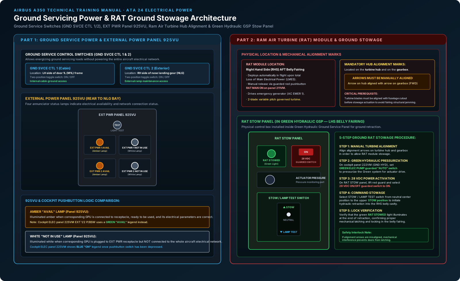
Ground Service Control Switches (GND SVCE CTL 1 & 2)
Servicing loads — including cabin cleaning lighting, ground utility receptacles, cargo door operation, and ground hydraulic servicing — can be energized without powering the primary flight avionics, cooling packs, or flight control computers. This is accomplished using two independent, two-position toggle switches:
- GND SVCE CTL 1 (Cabin Location): Installed inside the main passenger cabin on the left-hand frame of Door 1L (M1L). Flight attendants or cabin maintenance staff can toggle this switch to
ONupon entry to illuminate cabin servicing lights directly from an available ground power unit. - GND SVCE CTL 2 (Ramp Exterior Location): Installed on the exterior of the aircraft on the right-hand structure of the Nose Landing Gear (NLG). Ramp service personnel can activate ground servicing power directly from the tarmac without climbing into the cockpit.
Actuating either switch to ON closes the Ground Service Contactor (GSC), routing external power receptacle 1 (GPU 1) directly to the Ground Service Busbars without closing the main External Power Line Contactor (EPLC 1).
External Power Panel 925VU (Aft of NLG Bay)
The primary ground power interface is mounted at the rear of the nose landing gear wheel bay on Panel 925VU. The panel accommodates connections for two independent 90 kVA Ground Power Units (EXT PWR 1 and EXT PWR 2), a LIGHT TEST pushbutton, and four critical status indicator lamps:
| Panel 925VU Annunciator | Color & State | System Condition & Electrical Logic |
|---|---|---|
EXT PWR 1 AVAIL /EXT PWR 2 AVAIL | Amber (Steady) | GPU cable is plugged into the receptacle, the ground power source is running, and its electrical parameters (voltage, frequency, and phase sequence) have been verified as within nominal tolerances by the External Power Logic Controller (EPLC). The source is ready for use. |
EXT PWR 1 NOT IN USE /EXT PWR 2 NOT IN USE | White (Steady) | GPU cable is connected to the receptacle, but its power is NOT connected to the whole aircraft electrical network. The cockpit EXT 1/2 pushbutton switch on panel 225VM has not been depressed (or has been released). |
Operational Annunciation Difference: Cockpit vs. Ramp
Line engineers must note an important contrast in color coding between panel 925VU and overhead panel 225VM:
- On external panel 925VU, available power is annunciated by an amber AVAIL lamp.
- In the cockpit (Panel 225VM), available power is annunciated by a green AVAIL legend inside the pushbutton switch, and a blue ON legend when actively feeding the network.
04 · Multi-Voltage Architecture
Multi-Voltage Distribution Network: 230 VAC, 115 VAC & 28 VDC
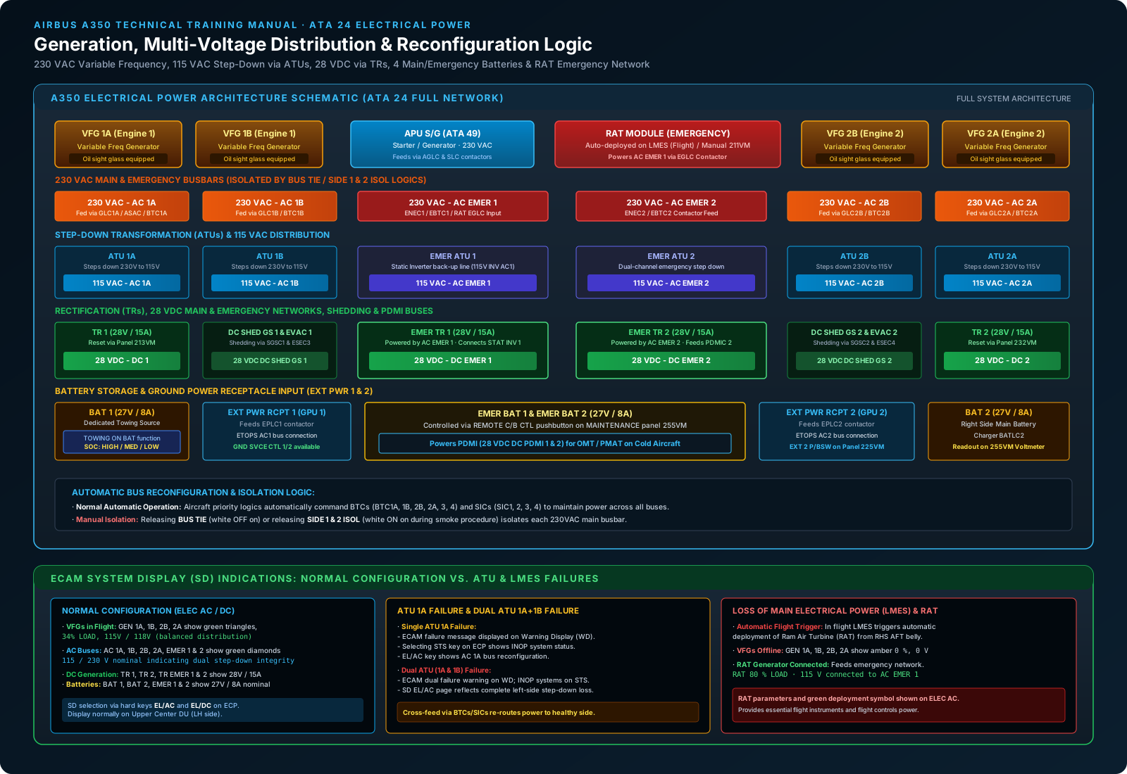
The A350 electrical architecture, outlined in detail on page 18 of the maintenance manual, departs from older 115 VAC-centric designs. By adopting 230 VAC Variable Frequency generation, conductor cross-sectional area and cable weight are drastically reduced while delivering substantial power to large motor loads (such as electric hydraulic pumps, environmental control fans, and wing ice protection systems).
1. Primary Generation: 230 VAC Variable Frequency
In flight, primary electrical power is supplied by four engine-mounted Variable Frequency Generators (VFGs):VFG 1A and VFG 1B on Engine 1, and VFG 2B and VFG 2A on Engine 2. Each VFG is equipped with an integral oil sight glass for direct visual inspection of lubrication levels during pre-flight maintenance. Each VFG connects to its corresponding 230 VAC main busbar through a Generator Line Contactor (GLC):
VFG 1Afeeds 230 VAC busAC 1Avia contactorGLC 1A.VFG 1Bfeeds 230 VAC busAC 1Bvia contactorGLC 1B.VFG 2Bfeeds 230 VAC busAC 2Bvia contactorGLC 2B.VFG 2Afeeds 230 VAC busAC 2Avia contactorGLC 2A.
Auxiliary 230 VAC power is provided by the APU Starter/Generator (APU S/G), which connects through the Auxiliary Generator Line Contactor (AGLC) and Starter Line Contactor (SLC). When on the ground, External Power Receptacles 1 and 2 route 230 VAC through contactors EPLC 1 and EPLC 2 to feed side 1 and side 2.
2. Secondary Transformation: 115 VAC via Auto-Transformer Units (ATUs)
Because standard avionics, flight instruments, cockpit displays, and specific fuel pumps require 115 VAC, the A350 utilizes six high-efficiency Auto-Transformer Units (ATUs) to step down 230 VAC to 115 VAC without electrical isolation:
ATU 1A:Steps down 230 VAC from busAC 1Ato feed 115 VAC busAC 1A.ATU 1B:Steps down 230 VAC from busAC 1Bto feed 115 VAC busAC 1B.ATU 2B:Steps down 230 VAC from busAC 2Bto feed 115 VAC busAC 2B.ATU 2A:Steps down 230 VAC from busAC 2Ato feed 115 VAC busAC 2A.EMER ATU 1:Steps down 230 VAC from emergency busAC EMER 1to feed 115 VAC busAC EMER 1. It also features a cross-connection toSTATIC INVERTER 1(providing 115 V backup via line115V INV AC1).EMER ATU 2:Steps down 230 VAC from emergency busAC EMER 2to feed 115 VAC busAC EMER 2.
3. DC Conversion: 28 VDC via Transformer Rectifiers (TRs)
Conversion from alternating current to 28 VDC is accomplished by four Transformer Rectifiers:
TR 1:Powered from 230 VAC busAC 1A, delivers 28 VDC (nominal 28 V / 15 A) to main busDC 1. Resettable from cockpit panel 213VM.TR 2:Powered from 230 VAC busAC 2A, delivers 28 VDC to main busDC 2. Resettable from cockpit panel 232VM.EMER TR 1:Powered from emergency busAC EMER 1, supplies 28 VDC to emergency busDC EMER 1.EMER TR 2:Powered from emergency busAC EMER 2, supplies 28 VDC to emergency busDC EMER 2.
Specialized DC distribution buses branch from this core, including DC SHED GS 1 and DC SHED GS 2 (shed via contactors SGSC 1/2 and ESEC 3/4), evacuation buses DC EVAC 1/2, and the dedicated maintenance buses DC PDMI 1 and DC PDMI 2.
4. Battery Storage & Charging
Four 27 V nominal batteries maintain DC stability, provide cold aircraft starting, and back up flight-critical avionics:
BAT 1:Dedicated main battery, charged viaBATLC 1from busDC 1. Supplies the towing circuit.BAT 2:Dedicated main battery, charged viaBATLC 2from busDC 2.EMER BAT 1:Emergency battery, charged viaEBATLC 1from busDC EMER 1.EMER BAT 2:Emergency battery, charged viaEBATLC 2from busDC EMER 2.
05 · Reconfiguration & Shedding Logic
Bus Reconfiguration, Isolation Logic & Electrical Load Management (ELMF)
The A350 power network is designed to remain fully operative under single or multiple generator failures through automatic contactor management, while providing definitive crew overrides for abnormal procedures.
Automatic Bus Tie Contactors (BTCs) & System Isolation Contactors (SICs)
Under normal flight conditions, power sources operate isolated or parallel-reconfigured via solid-state logic controllers:
Bus Tie Contactors:ContactorsBTC 1A,BTC 1B,BTC 2B,BTC 2A,BTC 3, andBTC 4close automatically if a generator fails, transferring the unpowered busbar to an adjacent operating VFG, the APU generator, or external power.System Isolation Contactors:ContactorsSIC 1,SIC 2,SIC 3, andSIC 4reconfigure cross-side feeder lines to balance generator loads.
Manual Isolation Overrides
Two cockpit pushbuttons on panel 225VM can completely override this automatic logic:
- BUS TIE Pushbutton Switch: Releasing this switch to the
OFFposition (whiteOFFilluminated) locks open all BTCs and SICs. Each 230 VAC main busbar (AC 1A,AC 1B,AC 2B,AC 2A) is isolated to its dedicated source, preventing cross-feeding in the event of busbar faults or suspected short circuits. - SIDE 1 & 2 ISOL Pushbutton Switch: Designed specifically for the cockpit electrical smoke elimination procedure. Releasing this switch to the
ONposition (whiteONilluminated) isolates side 1 from side 2, forcing all cross-tie contactors open. The flight crew can then systematically depower one side of the aircraft to identify and eliminate the smoke source without risking total loss of the remaining healthy side.
Electrical Load Management Function (ELMF)
The ELM P/B on panel 225VM governs the Electrical Load Management Function. ELMF continuously calculates total electrical demand against available generator capacity:
- Pushed (Normal):
OFFlegend dark. If an engine or VFG fails, ELMF executes prioritized, sequential load shedding — disconnecting non-essential commercial loads (galley ovens, in-flight entertainment, secondary cabin lighting) to preserve full electrical power for flight controls, navigation, and fuel pumps. - Amber FAULT: Illuminates if the ELMF software application encounters internal processing errors or loses bus sensor inputs.
- Released (Inoperative): White
OFFilluminates. Automatic load shedding is inhibited, and shedding must be managed manually by the crew.
06 · Battery Operations & Ground Movement
Battery Management, Cold Aircraft Starting & Towing on Battery Power
The Airbus A350 features advanced battery health monitoring, cold aircraft maintenance access, and dedicated towing capabilities without requiring main aircraft electrical power.
Direct Battery Voltage Reading via Panel 255VM
On maintenance overhead panel 255VM, the 5-position rotary selector switch provides a hardwired, analog-to-digital measurement channel to a dedicated LCD voltmeter display. This allows line maintenance personnel to verify the static open-circuit voltage of any of the four batteries (BAT 1, BAT 2, EMER BAT 1, EMER BAT 2) prior to starting or dispatch. A nominal battery displays approximately 27.6 V to 28 V; voltages below dispatch thresholds indicate that charging or replacement is required.
Towing on Battery Power Architecture
Airport operations often require repositioning or towing an aircraft across active taxiways when neither ground power nor the APU is available. Legacy aircraft require running the APU solely to power exterior navigation lights and flight deck-to-tug intercoms.
The A350 solves this through the TOWING ON BAT POWER function on panel 255VM:
- Pressing the
POWERpushbutton switch on panel 255VM activates a dedicated static circuit directly from BAT 1. - This powers mandatory towing systems: VHF 1 radio, nose landing gear tow interphone, flight deck intercom, and external navigation/anti-collision towing lights.
- A vertical CHARGE annunciator continuously displays Battery 1 State of Charge (SOC):
- HIGH (Green): Battery 1 has >75% charge; extended towing authorized.
- MED (Amber): Battery 1 charge is moderate (50%–75%); towing permitted for limited duration.
- LOW (Red): Battery 1 charge is insufficient (<50%); towing on battery power is prohibited.
07 · Digital Circuit Protection
Circuit Protection: Solid-State (SSPC/RCCB) vs. Classical C/Bs
One of the most profound evolutions in ATA 24 on the A350 is the transition away from flight deck circuit breaker walls to a dual-tier circuit protection philosophy:
| System Attribute | Solid-State Power Controllers (SSPCs) & RCCBs | Classical Circuit Breakers (C/Bs) |
|---|---|---|
| Physical Location | Mounted inside modular Solid-State Power Distribution Centers (SSDCs) in the avionics bay. | Mounted on Electrical Power Distribution Centers (EPDCs) and Circuit Breaker Panels (CBPs) in the avionics bay. |
| Control Interface | Virtual control through maintenance HMIs: Onboard Maintenance Terminal (OMT), Portable Maintenance Access Terminal (PMAT), and Pilot/Copilot OIS. | Manual, physical operation only. Cannot be commanded or reset from any software terminal. |
| Operational Commands | Electronic commands: OPEN, CLOSE, LOCK, and TAG. | Physical pull to open, physical push to close/reset. |
| Safety Lockout / Tagout | Digital Tagging: The technician applies a digital lock and electronic tag with a maintenance reason and operator ID; software prevents remote or automatic closing. | Physical Safety Clips & Paper Tags: Technicians must physically enter the avionics bay, install a mechanical safety clip around the breaker collar, and attach a physical paper warning tag. |
| Trip Monitoring | Microprocessor monitored. Tripping generates an instant data packet to the FWS and reports directly on the ECAM C/B page. | Auxiliary sensing contact monitors trip status and transmits an indication to the CDS. |
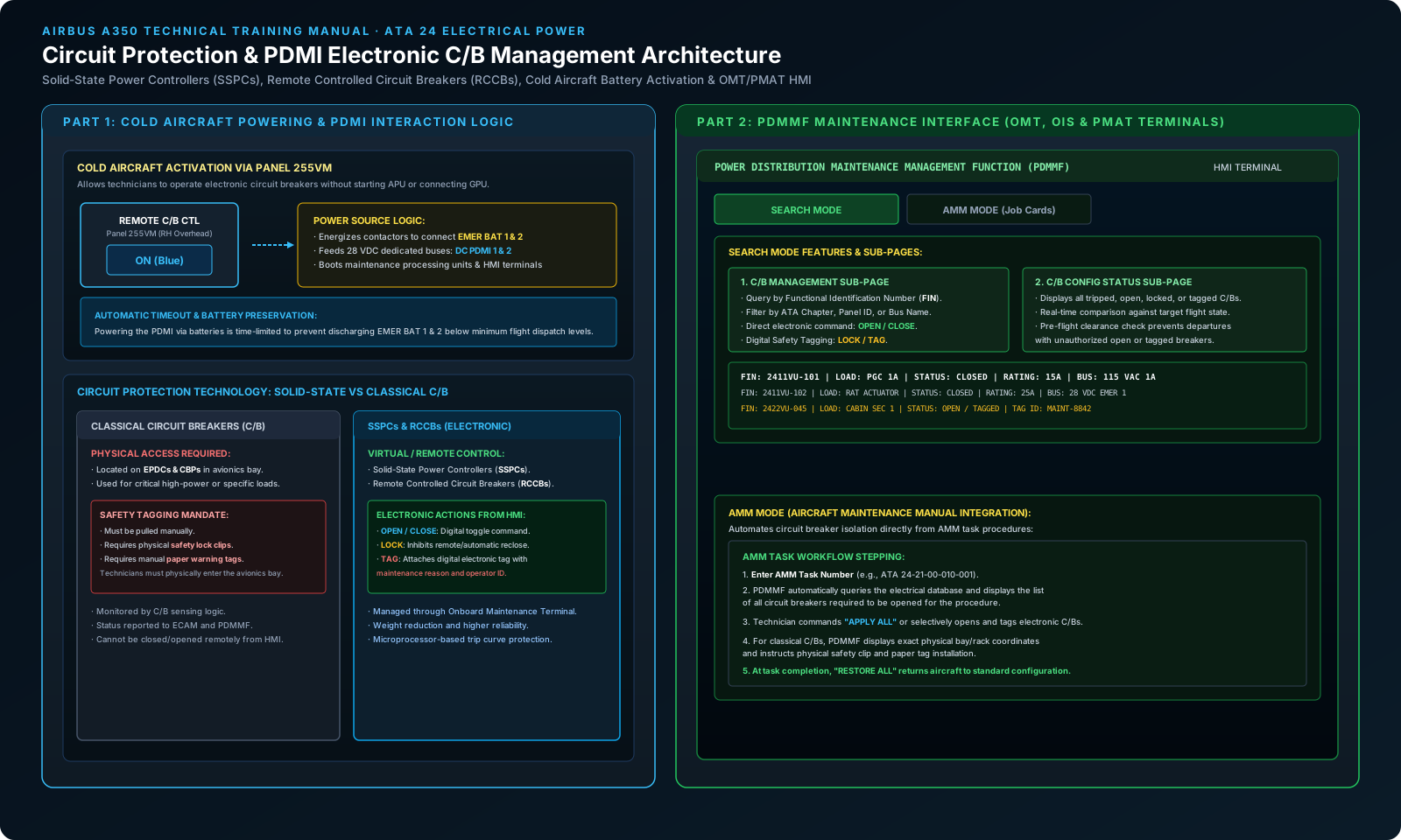
Cold Aircraft Powering: The REMOTE C/B CTL Logic
A common line maintenance dilemma on modern fly-by-wire aircraft is the need to isolate circuit breakers on an unpowered aircraft during towing or ramp parking. On the A350, technicians do not need to connect an external GPU or start the APU to open electronic breakers:
- The technician accesses cockpit maintenance overhead panel 255VM.
- Pressing the ELEC REMOTE C/B CTL pushbutton switch illuminates a blue
ONlegend. - This energizes dedicated battery feeder contactors, connecting EMER BAT 1 and EMER BAT 2 to 28 VDC distribution lines
DC PDMI 1andDC PDMI 2. - The Power Distribution Maintenance Interface (PDMI) processor boots up, energizing the Onboard Maintenance Terminal (OMT) in the cockpit and exterior Portable Maintenance Access Terminal (PMAT) receptacles.
- The technician opens, locks, or tags the required SSPCs or RCCBs directly from the screen. An automatic timer circuit prevents the batteries from draining below flight-dispatch limits.
08 · Maintenance Software Interface
PDMMF Maintenance Application: Search Mode & AMM Job Card Mode
Circuit protection management on the Onboard Maintenance Terminal (OMT) and PMAT is driven by the Power Distribution Maintenance Management Function (PDMMF) software application. PDMMF operates in two primary modes:
1. Search Mode
Search Mode is used for ad-hoc inspection and system troubleshooting. It contains two functional sub-pages:
- C/B Management: Allows the technician to search for any circuit breaker on the aircraft by entering its Functional Identification Number (
FIN), ATA chapter (e.g., ATA 23, 24, 27, 29), physical panel location, or load designation. Selecting an electronic breaker displays its current electrical state (CLOSED, OPEN, TRIPPED, LOCKED, or TAGGED), current load rating, and bus supply. The technician can executeOPEN,CLOSE,LOCK, orTAGcommands directly from the screen. - C/B Config Status: Displays a comprehensive summary of all circuit breakers across the entire aircraft that are currently tripped, open, locked, or tagged. Before aircraft dispatch, technicians review this page to ensure no maintenance tags remain on flight-critical systems.
2. AMM Mode (Aircraft Maintenance Manual Integration)
AMM Mode bridges digital circuit breaker control directly with official Airbus maintenance procedures:
- The technician inputs the specific AMM Task Number (e.g.,
24-21-00-010-001) from their work card into the PDMMF interface. - PDMMF queries its internal database and automatically generates the complete list of circuit breakers required to be opened to electrically isolate the system.
- The technician can select
APPLY ALLto automatically open and lock all electronic SSPCs and RCCBs associated with the task in a single operation. - For any classical electro-mechanical C/Bs involved in the task, PDMMF displays their exact physical panel and rack coordinates in the avionics bay, prompting the technician to physically pull them and install mechanical safety clips and paper tags.
- Upon task completion, selecting
RESTORE ALLcloses and un-tags all electronic breakers, returning the aircraft to its standard configuration.
09 · Emergency Generation & Ground Servicing
Emergency Electrical Power & RAT Ground Stowage Procedure
When all primary alternating current generation is lost in flight, the emergency electrical system ensures aircraft survivability via the Ram Air Turbine (RAT).
RAT Physical Location & Deployment
The RAT module is housed inside the Right Hand Side (RHS) AFT belly fairing. It deploys automatically in flight upon total Loss of Main Electrical Power (LMES), or manually when the red guarded RAT MAN ON pushbutton on cockpit panel 211VM is depressed. Once deployed, the two-blade variable-pitch turbine drives an emergency electrical generator, connecting to 230 VAC bus AC EMER 1 via contactor EGLC.
Mandatory Hub Alignment Marks
Critical Maintenance Interlock: Turbine Hub-to-Gearbox Alignment
Before initiating ground retraction and stowage of the deployed RAT, maintenance personnel MUST manually align the alignment marks (arrows) located on the turbine hub and on the gearbox.
Because the RAT turbine blades must align precisely with the fuselage belly cutout opening, attempting to retract the RAT without aligning these arrows will cause the turbine blades to strike the fairing structure, preventing latching and causing severe mechanical damage.
Step-by-Step RAT Ground Stowage Procedure
Ground stowage of the RAT is executed through the RAT Stow Panel, which is located inside the Green Hydraulic Ground Service Panel (GSP) in the Left Hand Side (LHS) belly fairing:
- Manual Alignment: Manually rotate the turbine blades until the alignment arrow on the turbine hub aligns with the arrow on the gearbox forward face.
- Pressurize Green Hydraulics: On cockpit overhead panel 222VM (GND HYD), set the
GREEN ELEC PUMPguarded "AUTO" pushbutton switch to pressurize the Green hydraulic circuit to nominal operating pressure. - Power Stow Panel: At the Green Hydraulic GSP on the LHS belly fairing, lift the red guard and select the
28 VDC ON/OFFswitch on the RAT Stow Panel toON. - Command Stowage: Move the three-position
STOW / LAMP TESTtoggle switch from its neutral center position to the upperSTOWposition. This commands the hydraulic retraction actuator to hoist the RAT module into the RHS belly fairing. - Verify Latch: Confirm that the green RAT STOWED light on the RAT Stow Panel illuminates at the end of retraction, verifying that the mechanical latching mechanism is securely locked. Return the 28 VDC switch to OFF and lower the guard.
10 · Degradation & Failure Modes
ECAM Failure Modes: Single/Dual ATU Faults & Total Loss (LMES)
The ECAM System Display and Warning Display provide clear, definitive indications during normal and abnormal network states:
1. Normal In-Flight Configuration (Page 15)
When selecting the EL/AC key on ECP 135VM during normal flight:
- All four VFGs (
GEN 1A,GEN 1B,GEN 2B,GEN 2A) display green triangles with balanced percentage loads (nominal ~34% load each). - All six 230 VAC and 115 VAC busbars display green diamond symbols and nominal voltages (230 V on primary buses, 115 V on ATU outputs).
- Selecting the
EL/DCkey shows all four TRs operating at 28 V / 15 A, with all four batteries showing nominal 27 V / 8 A in trickle-charge status.
2. Single ATU 1A Failure (Page 16 Left)
If Auto-Transformer Unit 1A experiences an internal failure or thermal trip:
- The Warning Display (WD) flashes an amber caution message:
ELEC ATU 1A FAULT. - Pressing the
STSkey on ECP 135VM displays the inoperative system status, detailing secondary systems depowered on 115 VAC busAC 1A. - Pressing the
EL/ACkey displays the reconfigured synoptic: busbarAC 1Ais cross-fed from adjacent ATUs via tie contactors, restoring essential instruments.
3. Dual ATU (1A & 1B) Failure
If both left-side step-down transformers (ATU 1A and ATU 1B) fail simultaneously:
- Dual amber caution messages appear on the WD:
ELEC ATU 1A FAULTandELEC ATU 1B FAULT. - The left-hand 115 VAC distribution network loses its dedicated step-down sources.
- The electrical logic commands Bus Tie Contactors and System Isolation Contactors (
BTC 1A,BTC 1B,SIC 1) to close, cross-feeding the healthy right-side ATU outputs (ATU 2AandATU 2B) across the tie bus to maintain left-side flight instruments.
4. Total Loss of Main Electrical Power (LMES) & RAT Deployment (Page 16 Right)
In the catastrophic event that all four engine VFGs go offline in flight:
- All four generator displays on the ELEC AC page change to amber crosses indicating
0 % LOAD, 0 V. - The FWS issues an emergency audio warning and displays red
ELEC EMER CONFIGwarnings on the Warning Display. - The Ram Air Turbine deploys automatically into the airstream from the RHS aft belly.
- Once the turbine reaches operating speed, contactor
EGLCcloses. - The ELEC AC synoptic displays the green RAT deployment symbol and dynamic electrical parameters: RAT 80 % LOAD, 115 V feeding emergency bus
AC EMER 1. - Static Inverter 1 (
STAT INV 1) and the emergency TRs energize critical flight control computers (PRIMs) and Captain flight displays.
11 · Field Engineering Reference
Line Maintenance Engineer's Field Guide
When troubleshooting and servicing ATA 24 on the A350 ramp or in the hangar, engineers must adhere to several operational protocols:
- Pre-Flight VFG Inspection: Always check the physical oil sight glasses on all four engine VFGs (
VFG 1A,VFG 1B,VFG 2B,VFG 2A) during walkaround. Low oil indications require servicing before dispatch. - Cold Aircraft Troubleshooting: Remember that pressing
REMOTE C/B CTLon panel 255VM powers the PDMI fromEMER BAT 1 & 2. Monitor battery voltages using the 255VM rotary voltmeter to ensure batteries are not depleted below minimum starting limits during prolonged troubleshooting. - Accessing the ECAM C/B Page: Do not search for a C/B button on the ECP. Use the SD rotary selector knob on the left of ECP 135VM to bring up the C/B page on the System Display.
- Servicing Power vs. Full Power: Use
GND SVCE CTL 1(cabin door 1L) orGND SVCE CTL 2(NLG) to power cleaning and utility loads without needlessly clocking hours on avionics cooling fans or primary computers. - Always Verify RAT Hub Alignment: Never command ground RAT stowage from the Green Hydraulic GSP without visually verifying that the hub and gearbox alignment arrows are perfectly aligned.
12 · Reference & FAQ
Frequently Asked Questions (FAQ)
How does the flight crew access the ECAM Circuit Breaker (C/B) page on the A350?
On the Airbus A350 center pedestal ECAM Control Panel (ECP 135VM), there is NO dedicated C/B push-button key. Instead, the flight crew and maintenance personnel access the C/B ECAM page using the SD rotary selector knob located on the left-hand side of the ECP, which displays the page on the System Display (SD) on the left side of the Upper Center Display Unit.
What is the difference between the AVAIL and NOT IN USE lamps on external power panel 925VU?
On external power panel 925VU (located aft of the nose landing gear bay), the amber AVAIL lamp illuminates when the ground power unit (GPU) is connected, ready to be used, and its electrical parameters are within correct tolerances. The white NOT IN USE lamp illuminates when the GPU is plugged into the receptacle but has not yet been connected to the aircraft electrical network (i.e., external power contactor EPLC is open and EXT P/BSW has not been selected ON).
How can technicians operate the PDMI electronic circuit breakers on a completely cold aircraft?
On a cold aircraft without ground power (GPU) or the APU running, technicians select the ELEC REMOTE C/B CTL pushbutton switch to ON (blue ON legend illuminated) on maintenance overhead panel 255VM. This commands dedicated contactors to connect Emergency Batteries 1 and 2 (EMER BAT 1 & 2) to feed 28 VDC power to the Power Distribution Maintenance Interface (PDMI via DC PDMI 1 & 2 buses), allowing electronic circuit breaker control via the Onboard Maintenance Terminal (OMT) or Portable Maintenance Access Terminal (PMAT).
What physical alignment is strictly required before stowing the Ram Air Turbine (RAT) on the ground?
Before stowing the RAT module on the ground, the alignment marks (arrows) located on the turbine hub and on the gearbox MUST be manually aligned. This positions the turbine blades correctly relative to the fuselage belly cutout to ensure the RAT module fits inside the cavity and allows the fairing doors to latch without structural interference.
What cockpit switch must be selected to pressurize the hydraulic system for ground RAT stowage?
Ground retraction and stowage of the RAT requires Green hydraulic system pressure. On cockpit overhead panel 222VM (GND HYD section), the GREEN ELEC PUMP guarded 'AUTO' pushbutton switch provides control to pressurize the Green hydraulic system on the ground for driving the RAT actuator.
How do Solid State Power Controllers (SSPCs) differ from classical circuit breakers in maintenance procedures?
Solid State Power Controllers (SSPCs) and Remote Controlled Circuit Breakers (RCCBs) are solid-state/remote devices managed electronically through cockpit HMIs (OMT, PMAT, OIS) with software OPEN, CLOSE, LOCK, and TAG functions. Classical circuit breakers (C/Bs) are physical electro-mechanical devices located on Electrical Power Distribution Centers (EPDCs) and Circuit Breaker Panels (CBPs) inside the avionics bay; they cannot be commanded electronically and require technicians to physically enter the avionics bay to pull them, apply mechanical safety clips, and attach physical paper warning tags.
What occurs on the ECAM System Display when total Loss of Main Electrical Power (LMES) occurs in flight?
Upon total Loss of Main Electrical Power (LMES) in flight, all four engine Variable Frequency Generators (VFGs) go offline, showing amber 0 %, 0 V indications on the ELEC AC page. The Ram Air Turbine (RAT) automatically deploys from the right-hand aft belly fairing. Once the emergency generator comes on line, the ELEC AC synoptic displays RAT electrical parameters (e.g., 80 % LOAD, 115 V) feeding the emergency network via AC EMER 1.
How does the TOWING ON BAT POWER function indicate battery readiness on panel 255VM?
Maintenance overhead panel 255VM contains a TOWING ON BAT POWER pushbutton switch and a dedicated CHARGE status annunciator. The CHARGE annunciator indicates Battery 1 State of Charge (SOC) via three distinct colored segments: green HIGH, amber MED, and red LOW, confirming whether BAT 1 has sufficient energy to power required towing equipment.
Official Technical Source Reference
- Document: Airbus A350 Technical Training Manual — Maintenance Course (T1+T2) (RR Trent XWB).
- Chapter: ATA 24 — Electrical Power — Electrical Power Control and Indicating (2/3).
- Applicability: Airbus A350-900 / A350-1000 Commercial Aircraft.
- Publication Notice: For training and reference evaluation only. Never use this guide to replace the approved Airbus Aircraft Maintenance Manual (AMM), Illustrated Parts Catalog (IPC), or Flight Crew Operating Manual (FCOM).