
01 · System Architecture
Architectural Overview of the Airbus A350 Communication System (ATA 23)
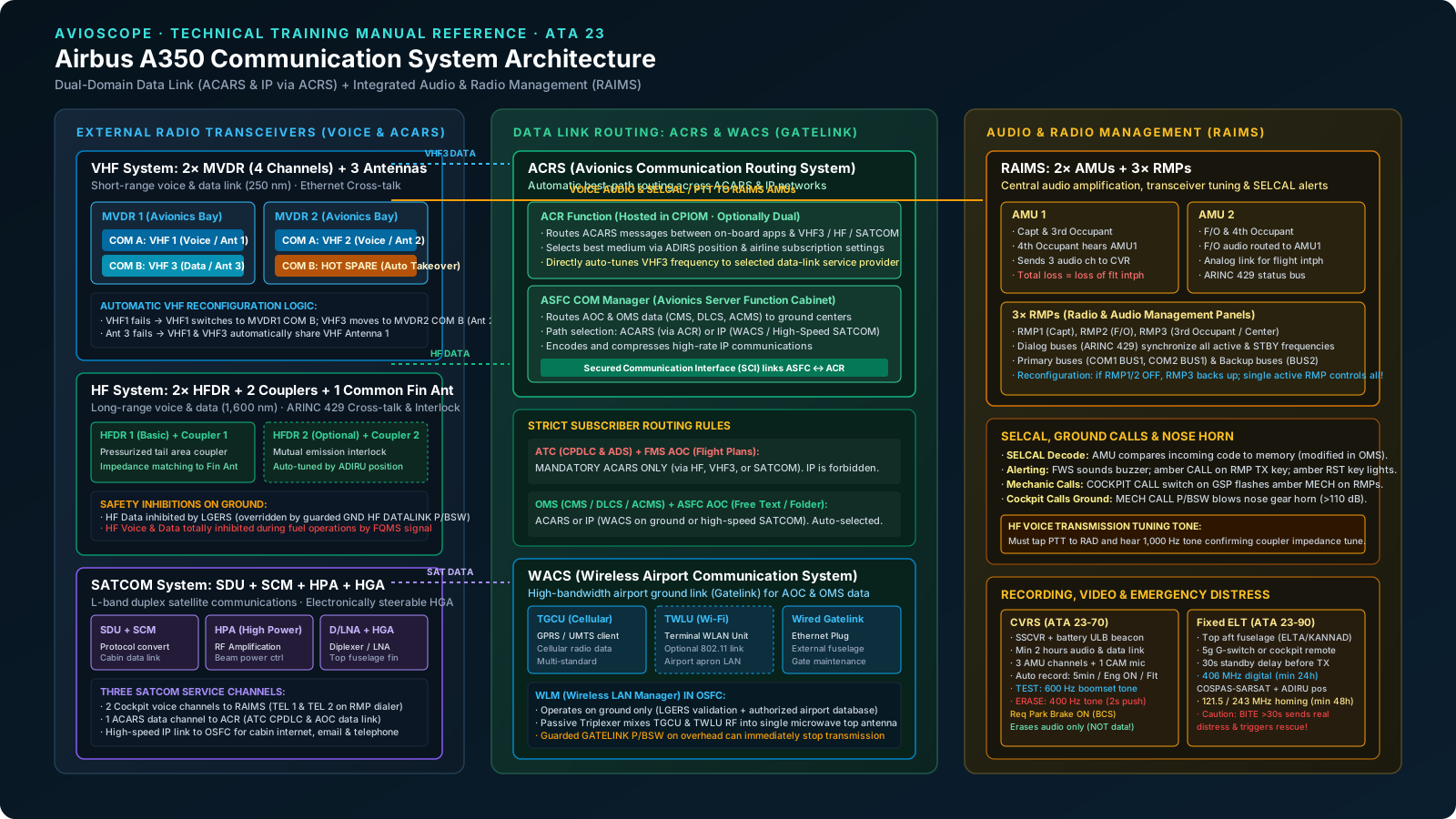
In 21st-century commercial transport operations, the aircraft communication suite is no longer a collection of standalone analog radios. On the Airbus A350, ATA Chapter 23 (Communications) represents a unified digital communications, acoustic processing, data-routing, external video, and emergency location network. The system provides two fundamental data and voice conduits:
- External Radio Frequencies: High Frequency (HF) and Very High Frequency (VHF) channels communicating with air traffic control (ATC) ground stations, airline operational control (AOC) centers, and other aircraft.
- Satellite Communications (SATCOM): L-band duplex satellite links providing worldwide voice connectivity for the flight crew and passengers, ACARS data link for oceanic operations, and high-speed Internet Protocol (IP) pipes for cabin services.
- Ground Gatelink (WACS): Wireless cellular (GPRS/UMTS), optional Wi-Fi (802.11), and physical Ethernet gatelink connections exchanging large data-loading files and maintenance reports while parked at the airport terminal.
- Acoustic & Audio Processing (RAIMS): Fully integrated digital and analog audio management controlling cockpit microphones, loudspeakers, interphone communications, navigation-aid aural identifiers, flight warning alerts, and Selective Calling (SELCAL).
- Recording & Emergency Systems: Solid State Cockpit Voice Recording (SSCVR) capturing four audio streams and written ATC data link messages, alongside an Automatic Fixed Emergency Locator Transmitter (ELT) radiating digital distress alerts to the international COSPAS-SARSAT satellite constellation.
02 · Short-Range Radio
VHF System: Dual MVDRs, 4 Channels & Hot-Spare Reconfiguration
The A350 VHF system provides short-range line-of-sight voice and data communications over an operational radius of approximately 250 nautical miles (nm). While previous aircraft architectures utilized three physically separate VHF transceiver boxes, the A350 utilizes advanced software-defined radios called Multiple VHF Data Radio (MVDR) units.
MVDR Architecture & Channel Allocation
The aircraft is equipped with two identical MVDR units installed in the main avionics compartment, coupled tothree identical blade antennas mounted on the fuselage (Antennas 1 and 3 on the upper fuselage, Antenna 2 on the lower fuselage). Each MVDR unit houses two completely independent transceivers designated Communication (COM) A andCommunication (COM) B, providing four available VHF channels:
| VHF Channel | Hardware Transceiver | Antenna Assigned | Normal Operational Function |
|---|---|---|---|
| VHF 1 | MVDR 1 — COM A | VHF Antenna 1 (Top) | Captain & flight crew primary voice communication |
| VHF 2 | MVDR 2 — COM A | VHF Antenna 2 (Bottom) | First Officer & flight crew secondary voice communication |
| VHF 3 | MVDR 1 — COM B | VHF Antenna 3 (Top) | Dedicated data link communication (ACRS) / Backup voice |
| VHF Standby | MVDR 2 — COM B | Unassigned (Hot Spare) | Operational Hot Spare; ready for instant automatic takeover |
The two MVDR units are interconnected through a dedicated Ethernet link, allowing continuous high-speed exchange of operational health status, channel allocations, and failure states.
Automatic Reconfiguration Logic
If a hardware fault or internal component degradation disables an active transceiver or antenna, the system executes anautomatic reconfiguration to preserve voice and data availability without requiring manual crew intervention:
- Failure of VHF 1 (MVDR 1 COM A): The primary VHF 1 voice channel is automatically transferred onto the MVDR 1 COM B transceiver. The displaced VHF 3 data channel is automatically reconfigured onto the hot-spare MVDR 2 COM B transceiver. In this failure state, VHF 2 and VHF 3 share VHF Antenna 2.
- Failure of VHF 2 (MVDR 2 COM A): The VHF 2 voice channel is automatically transferred onto the hot-spare MVDR 2 COM B transceiver, restoring First Officer communications seamlessly.
- Failure of VHF Antenna 3: If Antenna 3 suffers damage or feeder fault, the VHF 1 channel (MVDR 1 COM A) and the VHF 3 data channel (MVDR 1 COM B) automatically share VHF Antenna 1 through internal switching relays.
03 · Long-Range Radio
HF System: HFDR Transceivers, Couplers & Ground Safety Interlocks
For oceanic, polar, and remote overland routes beyond line-of-sight VHF coverage, the A350 relies on High Frequency (HF) communications operating over a range of approximately 1,600 nautical miles (nm). The HF suite supports both long-range voice and HF data link communications.
HF Hardware Topology
The basic aircraft configuration features one HF system (HF 1), with provisions for an optional second system (HF 2). The architecture consists of:
- High Frequency Data Radio (HFDR) Transceivers: Two identical transceivers installed in the main avionics compartment (HFDR 1 basic, HFDR 2 optional). The transceivers exchange status through an ARINC 429 cross-talk bus.
- HFDR Couplers: Two identical antenna couplers (Coupler 1 basic, Coupler 2 optional) located in the pressurized aft fuselage compartment near the base of the vertical stabilizer. Couplers match the complex radio frequency impedance of the antenna to the 50-ohm transceiver transmission lines across the 2 to 30 MHz band.
- Common Fin Antenna: A single common notch/blade antenna integrated into the lower leading-edge root section of the vertical stabilizer.
- Mutual Emission Interlock: Because both couplers share a single antenna structure, an electronic interlock function strictly prevents one coupler from transmitting while the other is emitting RF energy, eliminating transmitter burnout.
Ground Safety Interlocks & Fuel Operation Protection
Due to high RF field intensity and the potential for electrical arcing in hazardous areas, the A350 incorporates two strict safety inhibitions governed by hardware logic:
| Inhibition Type | Triggering System | Scope of Inhibition | Override / Recovery Condition |
|---|---|---|---|
| Ground HF Data Lockout | LGERS (Landing Gear Extension & Retraction System) | HF data transmission automatically inhibited on ground | Guarded GND HF DATALINK pushbutton switch on the Maintenance Overhead Panel (ICP) overrides inhibition for maintenance testing. |
| Ground Refuel / Fuel Operations Lockout | FQMS (Fuel Quantity & Management System) | Both HF VOICE and HF DATA transmission completely inhibited on ground | Active during all refuel, defuel, and internal fuel transfer operations. Non-overridable safety protection against fuel vapor ignition. |
Voice Frequency Tuning & The 1,000 Hz Tone Sequence
When selecting a new HF frequency on the Radio and Audio Management Panel (RMP), the pilot must follow a specific tuning protocol:
- Press the HF main access key on the RMP.
- Press Line Selection Key 1 (LSK1) to select the HF1 STBY box (highlighted in blue).
- Input the numerical frequency via the alphanumeric keypad and validate with LSK1.
- Transfer the frequency to active status using Activation/Dialing Key 1 (ADK1).
- Press the HF1 transmission key (confirmed by three illuminated green bars).
- Push the HF1 reception knob and rotate the potentiometer to establish volume (a white skirt appears on the knob and a loudspeaker icon displays on the RMP).
- Tune Verification: Momentarily press the INT/RAD PTT switch to the RAD position and release. The coupler adjusts tuning elements, generating a steady 1,000 Hz audio tone in the headset. Once the 1,000 Hz tone silences, the antenna impedance match is locked, and the flight crew can key PTT to transmit.
04 · Satellite Communications
Satellite Communication (SATCOM): SDU, HPA & Electronically Steered HGA
The Satellite Communication (SATCOM) system provides full-duplex (simultaneous transmission and reception) multi-channel voice and data communications through geostationary satellite constellations. It operates across the aeronautical L-bandand is partitioned into two distinct physical subsystems:
1. Satellite Control Subsystem
- Satellite Data Unit (SDU): The primary computation and protocol conversion engine of the SATCOM suite. It converts cockpit analog/digital audio and aircraft bus data into L-band RF signals and vice versa. It manages data protocol processing for ACARS data links and high-speed IP services.
- SDU Configuration Module (SCM): Contains secure memory cards storing configuration parameters, network addresses, and operational profiles required for high-speed data link services.
- High Power Amplifier (HPA): Amplifies the low-level RF transmission signals from the SDU to the precise power levels demanded to maintain link margins with the satellite. The SDU dynamically transmits beam and power-control instructions to the HPA.
2. Antenna Subsystem
- Diplexer / Low Noise Amplifier (D/LNA): Combines and segregates the transmitted (Tx) and received (Rx) L-band signals, filtering out high-power transmitter harmonics while amplifying weak incoming satellite downlink signals.
- High Gain Antenna (HGA): Mounted on an aerodynamic adapter plate along the top crown of the fuselage. The HGA is an electronically steerable phased-array antenna. Using aircraft position data from the Air Data/Inertial Reference System (ADIRS) and satellite orbital ephemeris, the SDU calculates look angles and electronically steers the antenna beam without mechanical motors.
SATCOM Channel Allocation & Log-On Modes
The SDU allocates three distinct operational services across its internal channels:
- Two Cockpit Voice Channels: Interfaced directly into the Audio Management Units (AMUs) and RMPs. Flight crews can dial public telephone numbers or select pre-recorded numbers from the Owner Requirement Table (ORT) on the RMP TEL page.
- One Safety Data Link Channel: Interfaced to the Avionics Communication Router (ACR) for ATC (CPDLC/ADS), AOC, and Onboard Maintenance System (OMS) messages. A second channel can be connected in dual-ACR configurations.
- One High-Speed IP Data Pipe: Interfaced via an Ethernet link to the Open world Server Function Cabinet (OSFC) Communication Manager to support passenger and cabin crew telephone, SMS, email, and high-speed internet access.
Log-On Behavior: SATCOM logs on automatically when the aircraft electrical network is energized, provided valid position data is output by ADIRS and the aircraft is within satellite coverage. Manual log-on can be initiated via the RMP SATCOM CONFIG / SETTINGS page by selecting specific Ground Earth Stations (GES) and satellite satellites.
05 · Digital Routing
Avionics Communication Routing System (ACRS): ACARS vs. IP Networks
The Avionics Communication Routing System (ACRS) is the central software router that manages all data link exchanges between the A350 and ground networks. It directs data across two primary media domains: traditional ACARS networks and high-throughput Internet Protocol (IP) networks.
Dual-Application Architecture: ACR & ASFC COM Manager
The ACRS function is split between two separate processing environments to ensure airworthiness segregation:
- Avionics Communication Router (ACR) Application: Hosted in a Core Processing Input/Output Module (CPIOM). The ACR manages the routing of flight-critical ACARS messages to and from HF, VHF 3, or SATCOM. Based on airline service provider subscriptions and current ADIRS position (evaluating VHF line-of-sight vs. SATCOM footprints), the ACR automatically selects the optimal link. Crucially, the ACR directly and automatically tunes the VHF 3 channel frequency to match the local VHF data link provider.
- ASFC Communication (COM) Manager: Hosted in the Avionics Server Function Cabinet (ASFC). It handles non-critical AOC and OMS data, performing protocol formatting, data encoding, and compression. It determines whether to route data over ACARS (via the ACR) or over IP (via WACS gatelink on ground or high-speed SATCOM in flight).
- Secured Communication Interface (SCI): All data passing between the ASFC COM Manager and the safety-critical ACR passes through a hardware-isolated Secured Communication Interface (SCI), preventing open-world IP traffic from corrupting flight avionics.
Strict Subscriber Routing Matrix
| Subscriber Application | Hosting Location | Permitted Transmission Means | IP Network Permitted? |
|---|---|---|---|
| Air Traffic Control (CPDLC & ADS) | CPIOM (Aircraft Control Domain) | ACARS only (VHF 3, HFDR, or SATCOM) | STRICTLY FORBIDDEN |
| FMS AOC (Flight Plans & Performance) | Flight Management Computer (FMC) | ACARS only (VHF 3, HFDR, or SATCOM) | STRICTLY FORBIDDEN |
| OMS (CMS, DLCS, ACMS Reports) | ASFC (Avionics Server Cabinet) | ACARS or High-Speed IP Network | YES (WACS or SATCOM SBB) |
| Airline Operations (Flight Folder, Text) | ASFC (Avionics Server Cabinet) | ACARS or High-Speed IP Network | YES (WACS or SATCOM SBB) |
06 · Airport Ground Link
Wireless Airport Communication System (WACS / Gatelink)
When parked at the airport gate or remote apron, uploading multi-gigabyte software packages (DLCS) or offloading complete flight data recorder dumps via narrow-band ACARS is impractical. The Wireless Airport Communication System (WACS), commonly termed Gatelink, delivers high-bandwidth wired and wireless connectivity between the aircraft and the airline LAN.
WACS Hardware Components
- Terminal GPRS/UMTS Client Unit (TGCU): A multi-standard cellular radio transceiver converting avionics IP packets into commercial cellular network protocols.
- Terminal Wireless LAN Unit (TWLU): An optional 802.11 Wi-Fi transceiver connecting into airport terminal wireless networks.
- Passive Triplexer: A passive RF mixing unit installed whenever both TGCU and TWLU are fitted. It combines cellular and Wi-Fi radio frequencies onto a single coaxial feed to the top-mounted WACS microwave antenna.
- Wired Gatelink Receptacle: A weather-sealed external Ethernet plug located on the lower fuselage allowing physical cat-5/fiber connection to ground servicing carts.
WLM Control & Guarded Ground Shutoff
WACS operations are orchestrated by the Wireless LAN Manager (WLM) software residing in the OSFC. Before energizing radio transceivers, the WLM verifies three criteria:
- The aircraft is confirmed on the ground via weight-on-wheels signals from LGERS.
- The airport position (latitude/longitude from ADIRS) is verified against an approved airport database for authorized radio use.
- The guarded GATELINK pushbutton switch on the overhead panel is in the normal (not OFF) position.
Pressing the guarded GATELINK P/BSW to OFF immediately removes power from the transceivers, inhibiting all wireless emissions during hazardous ramp operations.
07 · Audio & Acoustics
Radio & Audio Integrating Management System (RAIMS) & Dual AMUs
The Radio and Audio Integrating Management System (RAIMS) provides centralized control over all flight crew voice communications, aural warnings, interphones, passenger address (PA) broadcasts, and navigation-aid audio reception.
Audio Management Unit (AMU) Partitioning
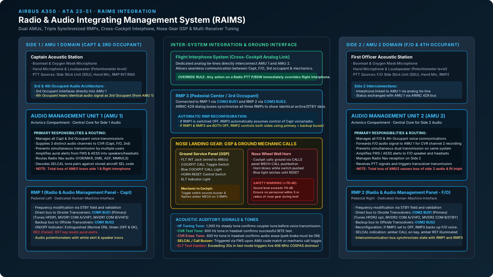
The core of RAIMS consists of two Audio Management Units (AMU 1 and AMU 2) installed in the main avionics bay:
- AMU 1 Domain: Manages audio inputs, outputs, amplification, and PTT routing for the Captain and3rd Occupant. AMU 1 also acts as the master collector for CVR recording, feeding three separate channels (Captain, First Officer, and 3rd Occupant) to the SSCVR.
- AMU 2 Domain: Manages audio processing for the First Officer and 4th Occupant. AMU 2 routes the First Officer's audio signal over a dedicated bus to AMU 1 for CVR encoding.
- 4th Occupant Acoustic Tie: The cockpit occupant seated at the 4th occupant station is hardwired to receive the exact identical audio feed as the 3rd occupant (derived directly from AMU 1).
- Failure Consequence: Total loss of either AMU causes the complete loss of all communications on that crew side and causes total loss of the flight interphone.
Flight Interphone & Nose Landing Gear Ground Service Panel (GSP)
The Flight Interphone connects the flight crew stations and ground mechanics through hardwired analog tie-lines linking AMU 1 and AMU 2. Ground personnel plug standard aviation headsets into the FLT INT jack on theGround Service Panel (GSP) located on the nose landing gear (NLG).
Priority Override Rule: If an occupant is speaking on the flight interphone, activating any radio Push-to-Talk (PTT) switch on a side stick, hand microphone, or RMP immediately overrides and mutes the flight interphone transmission.
Cockpit / Ground Mechanic Call Logic
- Ground Mechanic Calling Cockpit: The mechanic flips the COCKPIT CALL toggle switch on the GSP. This triggers a logic relay circuit sending a discrete to the AMUs. In response, an amber MECH legend flashes on all three cockpit RMPs for up to 60 seconds (or until answered), and the Flight Warning System (FWS) sounds a continuous buzzer. Pressing the RST button on any RMP silences the buzzer.
- Cockpit Calling Ground: A pilot presses the CALLS / MECH pushbutton on the overhead panel. This illuminates a bright blue COCKPIT CALL indicator light on the GSP and energizes the Nose Wheel Well Horn. The horn sounds continuously as long as the button is held. When released, the horn silences, but the blue light latches ON until the mechanic presses the HORN RESET toggle on the GSP.
08 · Crew Controls
Radio Management Panels (RMPs) & Multi-Receiver Tuning Hierarchy
Cockpit radio and audio control is concentrated across three identical Radio and Audio Management Panels (RMPs)installed on the center pedestal (RMP 1 on the Captain side, RMP 2 on the F/O side, and RMP 3 aft center).
Primary, Backup & Dialog Bus Network
Each RMP communicates with transceiver hardware over high-speed ARINC 429 digital buses structured into a fault-tolerant tree:
- RMP Intercommunication Bus: All three RMPs exchange frequency selections and standby buffer values via ARINC 429 dialog buses. Modifying a standby frequency on RMP 1 instantly updates RMP 2 and RMP 3, keeping all three displays perfectly synchronized.
- Primary Buses: RMP 1 controls onside transceivers (HFDR 1, MVDR 1 COM A, MVDR 1 COM B) via COM1 BUS1. RMP 2 controls onside transceivers (HFDR 2, MVDR 2 COM A, MVDR 2 COM B) via COM2 BUS1.
- Backup Buses: RMP 1 is wired to offside transceivers via COM1 BUS2; RMP 2 is wired to offside transceivers via COM2 BUS2. RMP 3 connects to RMP 1 via COM3 BUS1 and to RMP 2 via COM3 BUS2.
RMP Reconfiguration in Failure Scenarios
If an RMP fails or experiences a display freeze, setting its power switch to OFF initiates an automatic reconfiguration:
- Failure of RMP 1 or RMP 2: When the failed RMP is switched OFF, RMP 3 automatically assumes controlof that side's audio and voice communications. Transceivers continue to be tuned through the primary buses.
- Dual RMP Failure (RMP 1 + RMP 3 OFF): The single remaining operative panel (RMP 2) automatically controls all transceivers across both sides of the aircraft, driving onside radios via COM2 BUS1 and offside radios via backup bus COM2 BUS2.
RMP Annunciator Indications & SELCAL Decoding
The RMP integral ON/OFF Indicator provides distinct maintenance and operational statuses:
- Extinguished: RMP is powered ON and operating normally.
- Steady Green: RMP is switched OFF but internally healthy and operative.
- Steady Red: RMP has failed an internal BITE check (whether switched ON or OFF).
SELCAL Operation: When an incoming HF or VHF message matches the aircraft four-letter SELCAL code stored in AMU memory, an amber CALL legend illuminates on the respective transmission key, the amber RST legend lights up, and the FWS triggers an aural chime/buzzer. Selecting the transmission key connects the crew, turns the green bars on, extinguishes CALL, and resets the buzzer. Pressing RST silences the alert without answering.
09 · Video Systems
External Video System: TACS 1/3–2/3 Mosaic & 60-Knot Speed Inhibition
With a wingspan exceeding 64 meters, maneuvering the A350 along narrow taxiways and tight gate ramps demands visual guidance. The External Video System (ATA 23-81) provides real-time exterior views through two subsystems: theTaxiing Aid Camera System (TACS) and the optional Landscape Camera.
Camera Distribution & Concentrator Multiplexers (CMVs)
Three high-definition cameras transmit optical video feeds over fiber optic lines into two Concentrator and Multiplexer for Videos (CMVs):
- Belly TAC: Mounted on the lower forward fuselage, filming the nose gear and ground taxiway centerlines (routes to CMV 1).
- Vertical Stabilizer TAC: Mounted high on the vertical fin, filming the wings and main landing gear (routes to CMV 2).
- Landscape Camera: Mounted forward facing for passenger in-flight entertainment (IFE) views (routes to CMV 1).
- Optical Crosslink & Mosaic: CMV 1 and CMV 2 exchange video streams across a high-speed optical crosslink. The CMVs combine the two TACS feeds into a single composite mosaic image formatted on a 1/3 – 2/3 ratio(1/3 belly camera, 2/3 fin camera).
Cockpit Display Formats & 60-Knot PRIM Inhibition
The TACS mosaic can be presented on the Cockpit Display System (CDS) on either the Primary Flight Displays (PFDs) or the ECAM System Display (SD):
- PFD Display (TAXI Key on EFIS Panel): Displaying TACS on the Captain or F/O PFD is strictly restricted to ground operations. The video is available only when ground speed is not more than 60 knots.
- Automatic High-Speed Cutout: As the aircraft accelerates during takeoff roll and reaches 60 knots, the Flight Control Primary computers (PRIM) transmit a discrete inhibition signal deactivating the EFIS TAXI keys. The CDS immediately terminates the video display, returning the PFD to the standard attitude/flight director format.
- Landing Re-Arming: Following touchdown, once aircraft ground speed decelerates below 60 knots, the flight crew must re-press the TAXI key to restore the TACS mosaic on the PFD.
- ECAM SD Display (VIDEO Key): Unlike the PFD, the TACS and landscape feeds can be selected on the ECAM SD both on the ground and in flight without speed cutouts.
- CDS Data Overlays: The CDS receives ground speed from ADIRS and superimposes a numerical readout directly over the TACS mosaic, alongside visual alignment guide inserts calibrated via the Onboard Maintenance Terminal (OMT).
- TACS Lighting Interlocks: External high-intensity taxi lights illuminate only on ground, when TACS video is commanded, and when the runway turnoff / taxi camera switch on the external light panel is set to ON.
10 · Flight Recorders
Cockpit Voice Recording System (CVRS): Logic, Test & Erase Interlocks
The Cockpit Voice Recording System (CVRS) captures all cockpit audio interactions, aural alerts, engine sounds, and written data link exchanges for accident investigation in compliance with international airworthiness standards.
SSCVR Hardware & 4-Channel Recording Allocation
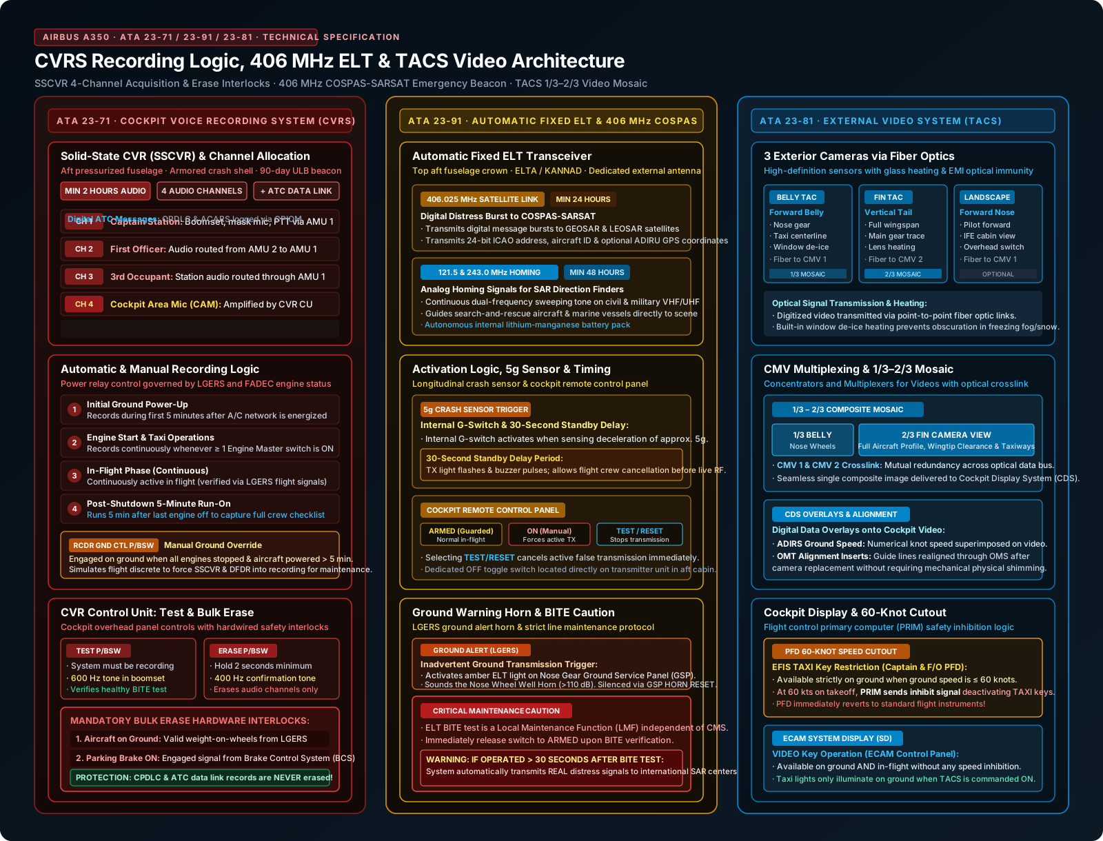
The central recorder is a Solid State Cockpit Voice Recorder (SSCVR) installed in the rear fuselage in a crash-resistant, fireproof armored shell fitted with a water-activated Underwater Locating Beacon (ULB). The SSCVR provides a minimum of two hours of continuous digital recording across four dedicated audio tracks:
- Channel 1: Captain boomset, oxygen mask mic, hand mic, and side stick PTT audio (supplied by AMU 1).
- Channel 2: First Officer audio (routed from AMU 2 through AMU 1).
- Channel 3: 3rd Occupant audio (supplied by AMU 1).
- Channel 4: Cockpit Area Microphone (CAM) mounted in the overhead panel, amplified by the CVR Control Unit (CU).
- Data Link Recording: In addition to voice, the SSCVR records all written digital ATC data link messages (CPDLC) received from CPIOMs.
Automatic & Manual Recording Relay Logic
The CVRS recording power circuit is governed by hardwired logic relays responding to flight and engine states:
| Mode | Operational Condition | Relay Logic / System Source |
|---|---|---|
| Automatic | Initial ground power-up | Records for the first 5 minutes after A/C electrical network is energized |
| Automatic | Engine start / Taxi | Continuously records whenever at least one Engine Master switch is set to ON |
| Automatic | In Flight | Continuously records in flight (confirmed by LGERS flight signal) |
| Automatic | Engine shutdown | Continues recording for exactly 5 minutes after the last engine shutdown |
| Manual | Maintenance ground operations | Pushing the RCDR GND CTL pushbutton on the overhead panel forces the SSCVR and DFDR into recording mode with engines stopped and electrical power on for > 5 minutes. |
BITE Test & Mandatory Bulk Erase Interlocks
The CVR Control Unit (CU) on the overhead panel provides a boomset monitoring receptacle and dual test/erase pushbuttons:
- BITE Test (TEST P/BSW): With the CVRS in recording mode, pressing TEST initiates a self-check. A successful test generates a loud 600 Hz audio tone in a headset connected to the CVR panel monitoring jack.
- Bulk Erase (ERASE P/BSW): To prevent accidental or unauthorized data loss, erasing the SSCVR memory requires holding the ERASE pushbutton for two seconds minimum under two strict, non-negotiable interlocks:
- The aircraft must be on the ground (LGERS weight-on-wheels relay).
- The parking brake must be confirmed set to ON by the Brake Control System (BCS).
- Critical Privacy Protection: The erase circuit wipes only the audio recording channels. In accordance with safety regulations, written ATC data link communications are never erased.
11 · Emergency Systems
Emergency Locator Transmitter (ELT): 406 MHz COSPAS & BITE Caution
The A350 Emergency Locator Transmitter (ELT) suite radiates emergency homing and satellite distress signals to facilitate rapid Search and Rescue (SAR) localization. The aircraft incorporates two ELT installations: an Automatic Fixed ELTand one or more Portable Survival ELTs.
Automatic Fixed ELT Specifications
- Location & Models: Installed in the upper crown aft fuselage section (ELTA or KANNAD models), connected via coaxial cable to a dedicated external whip antenna.
- Activation Triggers: Activates automatically when an internal deceleration sensor (G-switch) senses an impact deceleration of approximately 5g, or manually via the guarded Cockpit Remote Control Panel or local switch on the ELT.
- 30-Second Standby Delay: Upon G-switch impact detection, the ELT enters a 30-second standby period where the TX light and internal buzzer pulse intermittently. Once 30 seconds elapse, high-frequency pulsing commences, the remote panel ON light flashes, and live transmission begins.
- 406 MHz Digital Transmission (Min 24 Hours): Transmits digital burst messages on 406.025 MHz to theCOSPAS-SARSAT satellite constellation for at least 24 hours. The burst includes aircraft registration, operator code, and ELT serial data.
- Integrated Navigation Module (ADIRS GPS): When fitted with an optional navigation module, the ELT continuously memorizes aircraft latitude and longitude received from the ADIRUs via Common Remote Data Concentrators (CRDCs), encoding pinpoint coordinates directly into the 406 MHz satellite burst.
- 121.5 & 243 MHz Analog Homing (Min 48 Hours): Concurrently radiates continuous sweeping tones on civil (121.5 MHz) and military (243 MHz) distress frequencies for at least 48 hours to guide rescue aircraft homing DF receivers.
Ground Nose Gear Horn Activation
If an ELT is inadvertently triggered while the aircraft is parked on the ramp, the ground/flight relay (LGERS) immediately detects weight-on-wheels. It flashes the ELT indicator light on the Ground Service Panel (GSP) and sounds the Nose Landing Gear Horn. Ground mechanics can silence the horn by pressing the HORN RESET switch on the GSP, alerting maintenance that the cockpit remote panel must be switched to TEST/RESET.
CRITICAL MAINTENANCE CAUTION: 30-SECOND BITE LIMIT
The ELT Built-In Test Equipment (BITE) is a Local Maintenance Function (LMF) operating completely independent of the Central Maintenance System (CMS). Initiating the test via the cockpit remote control panel TEST/RESET switch checks unit integrity and antenna continuity.
MANDATORY ACTION: Immediately stop operation of the ELT once the BITE test sequence is finished. IF THE ELT OPERATES MORE THAN 30 SECONDS AFTER THE BITE TEST IS COMPLETED, IT WILL AUTOMATICALLY TRANSMIT LIVE DISTRESS SIGNALS. THIS WILL INITIATE REAL-WORLD SEARCH AND RESCUE (SAR) MOBILIZATION.
12 · Maintenance Engineering
Line Maintenance Engineer's Summary & Ground Call Horn Safety
To assist certified Part-66 / FAR-147 engineers and technicians performing pre-flight, daily, and turnaround checks, the following practical parameters summarize critical communications maintenance interfaces:
| System | Component / Panel | Routine Line Check / Maintenance Task | Critical Operational Precautions |
|---|---|---|---|
| VHF / MVDR | OMT Utilities > A/C COM Status | Verify MVDR 1 & 2 status; ensure hot spare COM B is available | If MVDR 1 COM A is deferred, verify VHF 2 & 3 antenna sharing configuration |
| HFDR | Overhead ICP Panel & RMP | Functional voice test: verify 1,000 Hz tuning tone in boomset | NEVER transmit on HF during refueling, defueling, or fuel transfer. FQMS lockout should prevent emission, but manual verification is mandatory. |
| RAIMS / Ground Horn | NLG Ground Service Panel (GSP) | Test MECH CALL toggle and verify blue light latch and horn reset | WARNING (>110 dB): Ensure no personnel are within 5 meters radius of the nose gear bay when testing the mechanic call horn. |
| CVRS | Overhead CVR CU Panel | Press TEST P/BSW; verify 600 Hz tone in headset | To erase: Parking brake MUST be set ON (BCS). Press ERASE for 2s minimum; verify 400 Hz tone. ATC data link messages are not affected. |
| ELT | Overhead Remote Panel | Check switch in ARMED position. Perform BITE test via TEST/RESET switch | DO NOT leave switch in test mode > 30 seconds. Unwanted live transmission initiates international rescue response. |
| TACS | EFIS & ECAM Control Panels | Verify mosaic format on SD and PFDs. Realign inserts via OMT if cameras replaced | PFD video is automatically inhibited when ground speed exceeds 60 knots. |
13 · Technical Reference
Frequently Asked Questions (FAQ)
How does the A350 VHF system provide four channels using only two MVDR units?
The A350 installs two identical Multiple VHF Data Radio (MVDR) units in the avionics compartment, but each MVDR contains two independent transceivers designated COM A and COM B. This produces four available VHF channels: MVDR 1 COM A operates VHF 1 (using Antenna 1 for flight crew voice), MVDR 2 COM A operates VHF 2 (using Antenna 2 for flight crew voice), MVDR 1 COM B operates VHF 3 (using Antenna 3 for data link to the ACR, with voice capability), and MVDR 2 COM B functions as a hot spare that automatically takes over if any operational channel fails.
What occurs during an automatic VHF reconfiguration if MVDR 1 COM A fails?
If MVDR 1 COM A fails, VHF 1 voice communication is automatically reconfigured onto the MVDR 1 COM B transceiver. To maintain data link capability, the VHF 3 data channel is automatically reconfigured onto the hot spare MVDR 2 COM B transceiver. In this reconfigured state, VHF 2 and VHF 3 share VHF Antenna 2.
What safety inhibitions govern HF voice and data transmission on the ground?
On the ground, HF data transmission is automatically inhibited by a ground signal from the Landing Gear Extension and Retraction System (LGERS); this inhibition can be overridden for maintenance via the guarded GND HF DATALINK pushbutton switch on the maintenance overhead panel. Furthermore, all HF transmissions (both voice and data) are completely inhibited on the ground during aircraft refueling, defueling, or fuel transfer operations via a dedicated safety interlock signal from the Fuel Quantity and Management System (FQMS).
Why must pilots wait for a 1,000 Hz tone when transmitting on HF voice?
When initiating an HF voice transmission, the pilot taps the PTT switch to the RAD position and releases it. This commands the HFDR coupler near the vertical stabilizer to perform RF impedance matching to the common fin antenna. The system emits a 1,000 Hz audio tone in the headset. Once the 1,000 Hz tone stops, the HF system is tuned and ready; the pilot then activates PTT again to speak.
What are the strict routing rules enforced by the ACRS for ATC vs. airline data?
Under the ACRS routing policy, safety-critical ATC communications (CPDLC, ADS, and aircraft reporting) and FMS AOC messages (flight plans) are mandatory ACARS-only and can only be routed over HF, VHF 3, or SATCOM; they cannot be routed over the IP network. In contrast, Onboard Maintenance System data (CMS, DLCS, ACMS) and ASFC flight crew AOC data (free text, flight folders) can be routed over either the ACARS network or high-bandwidth IP networks (WACS cellular/Wi-Fi on the ground or high-speed SATCOM in flight).
What conditions must be satisfied before the CVR can be erased on the ground?
The CVR bulk erase function operates only when two strict interlocks are met: 1) the aircraft must be on the ground (LGERS weight-on-wheels signal), and 2) the parking brake must be set to ON as confirmed by the Brake Control System (BCS). The operator must press the ERASE pushbutton on the CVR Control Unit for a minimum of two seconds. Successful erasure is confirmed by a 400 Hz tone in a boomset connected to the CVR panel. Crucially, the erase function clears only the audio channels; ATC data link message records are not erased.
Why does the A350 technical manual include a critical caution regarding the ELT BITE test?
The ELT self-test is a Local Maintenance Function (LMF) independent of the CMS. Maintenance personnel must immediately stop ELT operation once the self-test completes. If the ELT remains operated for more than 30 seconds after the BITE test is completed, the system will automatically transmit real 406 MHz emergency distress signals to the COSPAS-SARSAT satellite constellation and broadcast 121.5/243 MHz homing signals, initiating international search and rescue operations.
At what speed is the TACS video mosaic automatically inhibited on the PFDs?
TACS video images are displayed on the Captain and F/O PFDs only on the ground when aircraft ground speed is not more than 60 knots. When ground speed reaches 60 knots (such as during takeoff roll), the Flight Control PRIMary computers (PRIM) transmit a TACS inhibition signal to the EFIS control panels, deactivating the TAXI keys and removing the video mosaic from the PFDs. After landing, once ground speed decreases below 60 knots, the flight crew can re-select the TAXI keys to restore the mosaic.