
01 · System Overview
Overview of the Airbus A350 Data Loading System (ATA 45)
In modern fly-by-wire commercial aircraft, software constitutes the core intelligence of nearly every operational system. On the Airbus A350 XWB, software lifecycle management—encompassing routine navigation database cycles, operational software upgrades mandated by Service Bulletins (SB), and in-field line maintenance reloading—is governed by the Data Loading System, defined within ATA Chapter 45 (Onboard Maintenance System - OMS).
According to the Airbus A350 Technical Training Manual, the data loading system is designed to execute five fundamental functions:
| Function # | Operational Function | Functional Scope & Interface |
|---|---|---|
| 01 | Field Loadable Software Import | Importing Field Loadable Software (FLS) from a physical USB memory device or automatically from airline ground facilities via wireless networks. |
| 02 | Field Loadable Software Uploading | Transferring and flashing verified software loads into target aircraft computers, Line Replaceable Units (LRUs), and Line Replaceable Modules (LRMs). |
| 03 | Configuration Reporting & Storage | Acquiring, timestamping, validating, and persistently storing hardware and software part number configurations reported by target computers. |
| 04 | Repository Management | Maintaining segregated onboard database partitions (Inbox and Reference Repository) to support both software upgrade and software repair operations. |
| 05 | Data / File Downloading | Extracting operational, BITE, and maintenance data files from aircraft systems and transferring them to a USB device or to ground facilities. |
All data loading operations are accessible through the Human Machine Interfaces (HMIs)of the Onboard Maintenance System (OMS). Maintenance personnel interact with the system via theOnboard Maintenance Terminal (OMT), the Onboard Information System (OIS) display on the Control and Display System (CDS), or through the optional Portable Multipurpose Access Terminal (PMAT).
02 · Domain Segmentation
Dual Loading Architecture: DLCS-ACD (ASFC) vs. Simple Data Loader (OSFC)
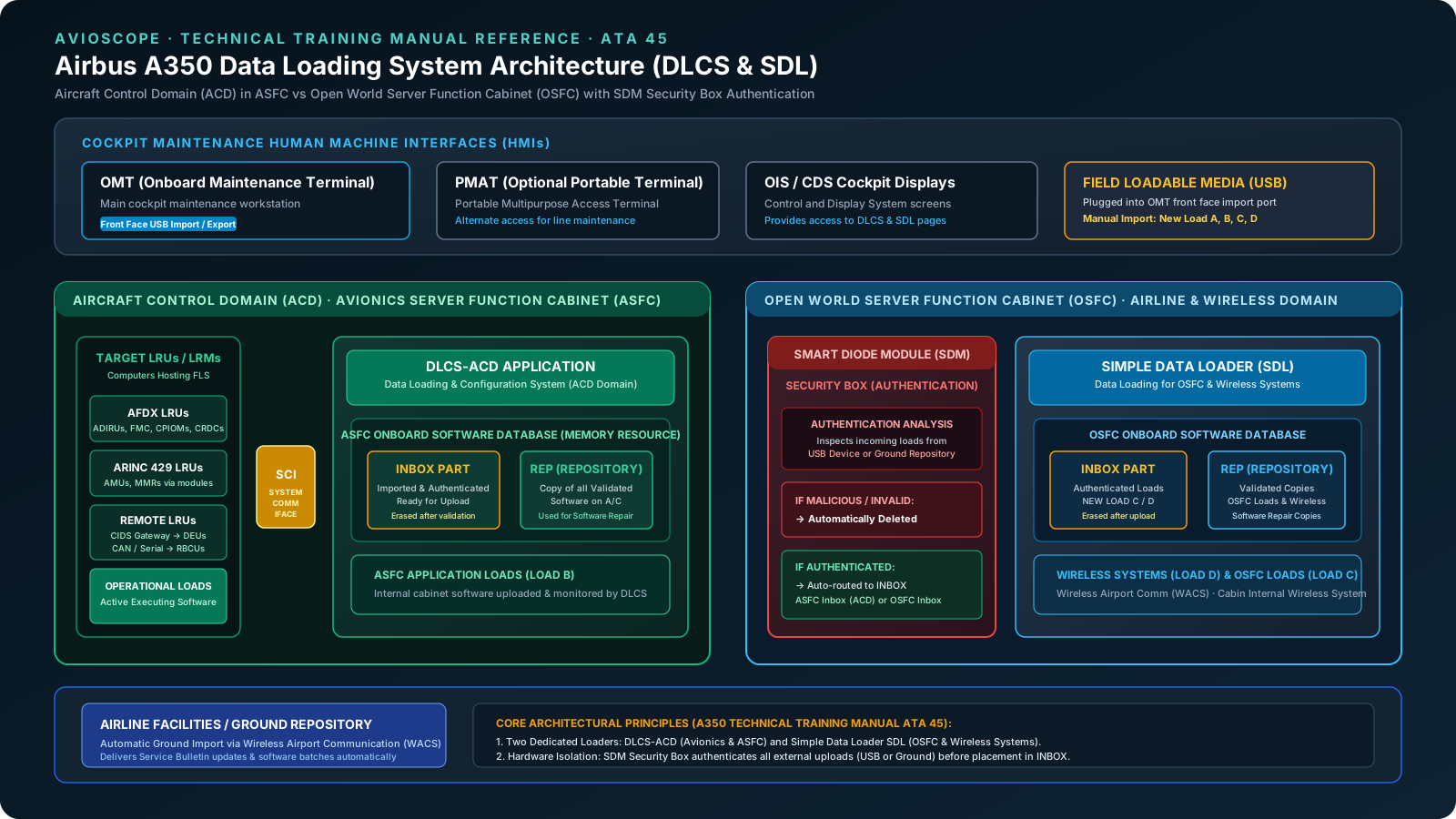
To maintain strict isolation between safety-critical flight systems and commercial open-world connectivity, the Airbus A350 data loading system is structured into two completely separate software applications hosted across two distinct avionics hardware cabinets:
- DLCS-ACD (Data Loading and Configuration System - Aircraft Control Domain): Hosted inside the Avionics Server Function Cabinet (ASFC). The DLCS-ACD application executes all data loading, configuration acquisition, and verification functions for the Aircraft Control Domain (ACD). This includes all flight-critical avionics LRUs connected via the aircraft's System Communication Interfaces (SCIs), as well as internal ASFC hosted application software (ASFC loads).
- SDL (Simple Data Loader): Hosted inside the Open world Server Function Cabinet (OSFC). The SDL application governs data loading functions for open-world equipment, specifically:
- The OSFC field loadable software (loads);
- The Wireless Airport Communication System (WACS) field loadable software;
- The cabin internal wireless system field loadable software.
Both the DLCS-ACD and the SDL manage their own dedicated onboard memory resources, structured identically into two operational areas: the Inbox area and the Repository area.
03 · Avionics Cyber-Security
Smart Diode Module (SDM): Security Box Authentication
Because modern airliners interface with ground repositories over public cellular/Wi-Fi links and accept commercial USB drives in the cockpit, cyber-security and software provenance are paramount. On the A350, all inbound software imports pass through a dedicated security gateway known as the Smart Diode Module (SDM), hosted in the OSFC.
SDM Security Filtering Logic
The SDM functions as an active hardware and cryptographic barrier. When a new software load arrives (whether transmitted wirelessly from airline facilities or uploaded locally via the OMT front-face USB import plug), the SDM security-box function performs rigorous integrity and cryptographic authentication:
- Malicious or Unauthenticated Load: If there is any indication that the software load is corrupted, altered, or malicious, the SDM automatically deletes the load immediately. No unverified binary can traverse into the aircraft system memory.
- Authenticated Load: If the software passes authentication, the SDM automatically routes and transfers the verified load into the appropriate INBOX partition: either into the ASFC Inbox (for ACD avionics computers) or into theOSFC Inbox (for open-world and wireless components).
This deterministic filter ensures that no software can be selected for installation on flight-critical computers without prior verification and cryptographic sign-off by the SDM.
04 · Data Distribution
DLCS Subscribers: AFDX, ARINC 429 & Remote Gateway LRUs
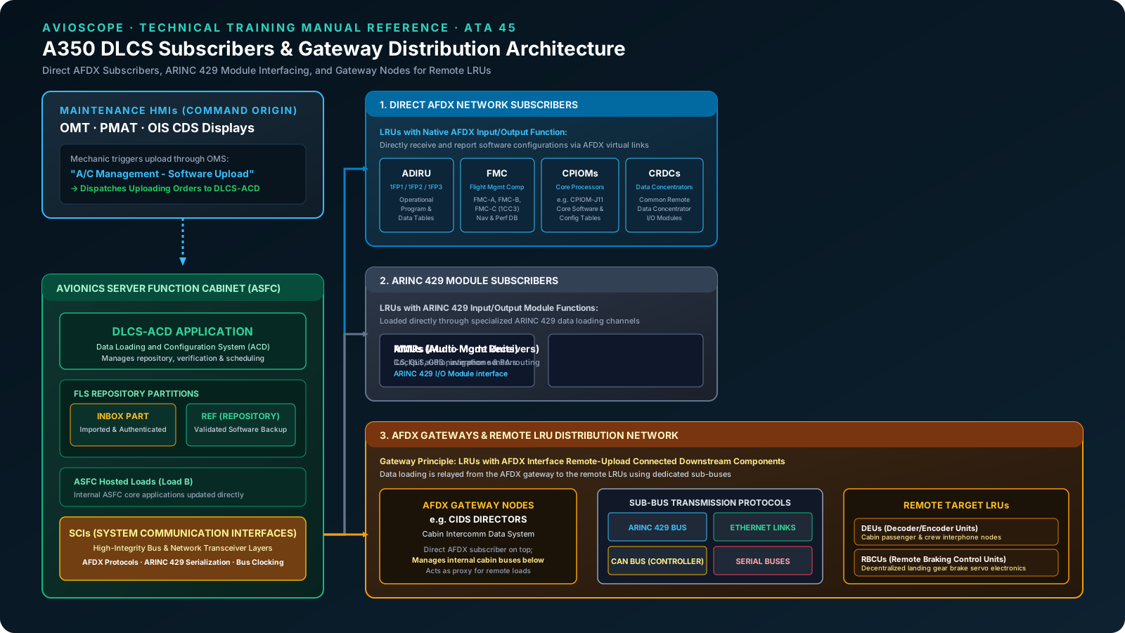
The DLCS-ACD in the ASFC is responsible for flashing software into the aircraft system computers via theSystem Communication Interfaces (SCIs). However, because of input/output bandwidth limitations and finite computing resources, the DLCS-ACD cannot interface with every single avionics box directly.
Instead, the A350 establishes three well-defined subscriber categories for data loading:
1. Direct AFDX Network Subscribers
Avionics computers equipped with native AFDX (Avionics Full-Duplex Switched Ethernet)input/output functions connect directly to the DLCS-ACD through virtual links. Key examples include:
- Air Data/Inertial Reference Units (ADIRUs): Such as 1FP1 (ADIRU 1), 1FP2 (ADIRU 2), and 1FP3 (ADIRU 3), receiving operational programs and data tables.
- Flight Management Computers (FMC): FMC-A, FMC-B, and FMC-C (e.g. FIN 1CC3), receiving navigation databases and performance models.
- Core Processing Input/Output Modules (CPIOMs): Integrated Modular Avionics (IMA) processors such as CPIOM-J11 hosting operational core software and configuration tables.
- Common Remote Data Concentrators (CRDCs): Distributed data acquisition nodes managing peripheral sensor inputs.
2. ARINC 429 Module Subscribers
Certain LRUs communicate over classic point-to-point avionics digital buses. For these units, the DLCS-ACD performs data loading through dedicated ARINC 429 input/output module functions:
- Audio Management Units (AMUs): Managing cockpit voice routing, radio communications, and interphone channels.
- Multi-Mode Receivers (MMRs): Precision landing and navigation sensors combining ILS, GLS, and GPS capabilities.
3. AFDX Gateway Subscribers & Remote LRUs
To avoid running heavy individual data loading lines to dozens of remote peripheral units distributed throughout the airframe, certain primary LRUs equipped with an AFDX interface operate asgateways. In this architecture:
- The DLCS-ACD uploads the package directly to the primary AFDX gateway computer over the high-speed network.
- The gateway computer takes custody of the data and relays the transmission downstream to remote components.
- Downstream transmission from the gateway to remote LRUs is conducted using specialized sub-buses, including:ARINC 429, Ethernet, Controller Area Network (CAN) bus, or serial buses.
Prominent examples of this gateway arrangement include:
- Cabin Intercommunication Data System (CIDS) Directors: The CIDS Directors receive cabin software over AFDX and act as gateways to flash Decoder/Encoder Units (DEUs)distributed across the passenger cabin.
- Remote Braking Control Units (RBCUs): Decentralized brake actuation controllers located near the landing gear bays, updated via gateway routing across serial or CAN interfaces.
05 · Memory Resource Management
Onboard Software Database: INBOX vs. REPOSITORY (REF) Partitions
A core design principle of the A350 OMS is the complete onboard availability of operational software. The onboard software database is a dedicated memory resource designed to maintain a local master copy of all field loadable software (loads) operating across the aircraft computers.
The aircraft houses two physical onboard databases:
- ASFC Database: Dedicated to all avionics LRUs and internal ASFC application software.
- OSFC Database: Dedicated to open-world applications, OSFC software, and wireless systems.
Each database is partitioned into two distinct functional zones:
| Partition | Contents & Status | Operational Purpose & Retention Rule |
|---|---|---|
| INBOX | Contains all newly imported (manually via USB or automatically from the ground) and authenticated software loads that are ready for uploading into target computers. | Acts as an active staging area. Critical Rule: Software is only removed or erased from the inbox when the uploading procedure and configuration validation are formally completed and confirmed via the DLCS HMI (i.e. configuration OK). |
| REPOSITORY (REP) | Contains an exact, validated copy of all field loadable software currently flashed and operating in the aircraft computers. | Serves as the onboard master backup for Software Repair. Whenever a computer exhibits abnormal operation or a replacement LRU is installed without pre-loaded software, the technician can restore the system immediately from the REP partition without needing a USB drive. |
06 · Maintenance Procedures
Software Upload Synoptic: Repair vs. Upgrade Workflows
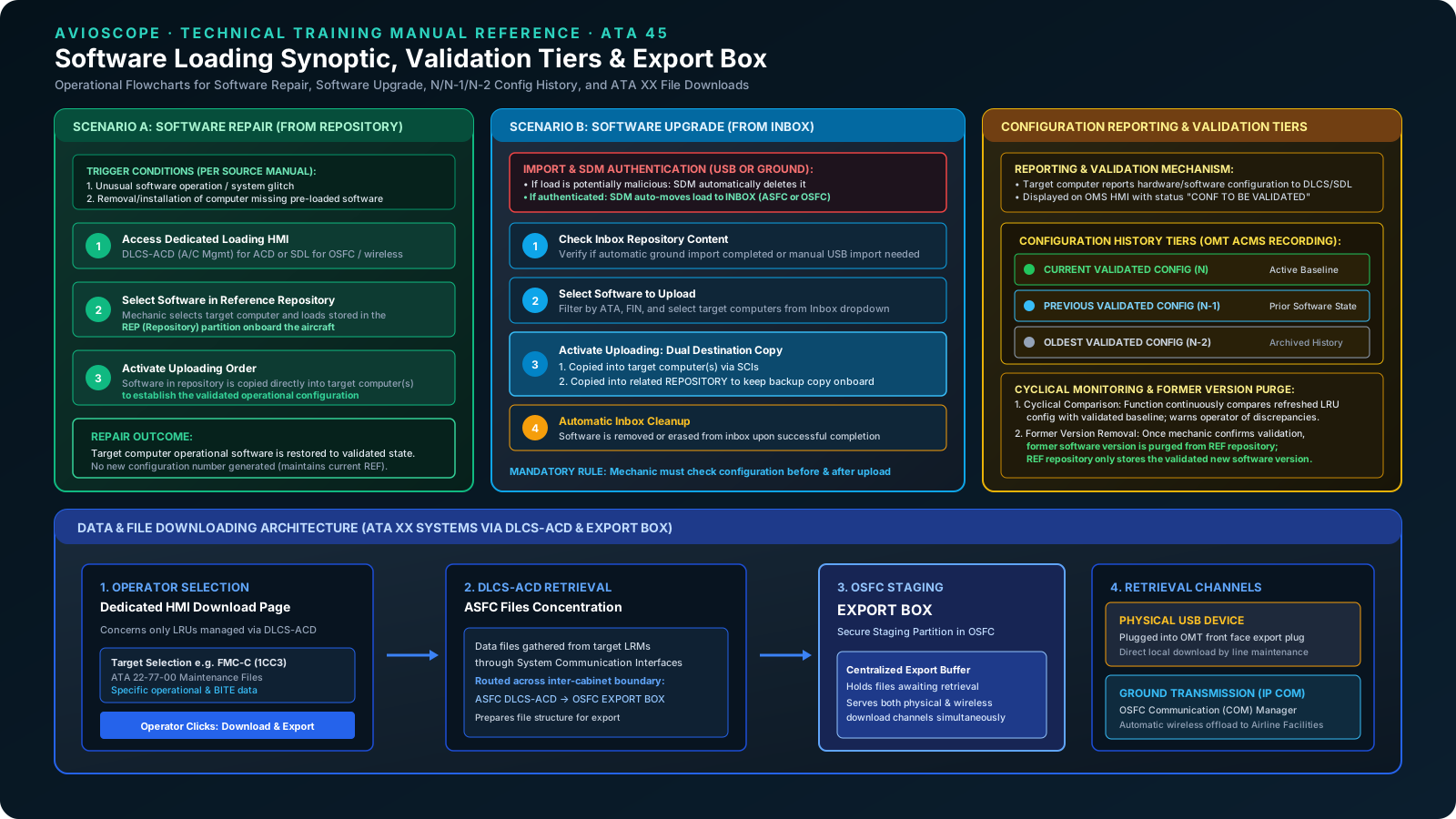
During aircraft servicing, software uploading is initiated under two distinct scenarios:Software Repair (restoring a known good state from the onboard repository) andSoftware Upgrade (installing a newer version from the inbox).
Scenario A: Software Repair (From Repository)
Software uploading directly from the onboard repository is executed in two specific maintenance circumstances:
- An unusual software operation: Correcting a transient glitch, operational anomaly, or corrupted memory sector.
- Removal or installation of a hosting computer: When a replacement LRU is installed on the aircraft and the required operational software was not pre-loaded prior to installation (software missing).
Repair Workflow:
- The mechanic navigates to the appropriate data loading HMI (DLCS-ACD for avionics, SDL for open world).
- The mechanic selects the target computer and specifies the required software stored in the REP (Repository) partition.
- Upon activation of the uploading order, the software from the repository is copied directly into the target computer(s), quickly restoring the validated aircraft configuration.
Scenario B: Software Upgrade (From Inbox)
A software upgrade is performed when introducing a new software revision, such as updating a navigation database or incorporating an Airbus Service Bulletin (SB).
Upgrade Workflow:
- The mechanic opens the dedicated data loading HMI (DLCS-ACD or SDL).
- The mechanic performs a check of the INBOX repository:
- Case 1 (Inbox is complete): If the required software version has already arrived via automatic ground transfer, the mechanic selects the software directly.
- Case 2 (Inbox is empty or files are missing): The mechanic performs a manual import by inserting a USB device into the OMT front face import port. The SDM authenticates the files and places them into the inbox. The mechanic then selects the software.
- The mechanic initiates the uploading order. The software in the inbox is copied simultaneously into:
- The target computer(s) across the SCIs;
- The related onboard repository (REP) to establish the new onboard baseline.
- Once the upload and configuration validation succeed, the software is automatically erased from the inbox.
07 · Cockpit Interface
Cockpit Maintenance HMIs: OMT, PMAT & OIS CDS Display Formats
Maintenance operators command and monitor all data loading operations using the cockpit maintenance HMIs. Crucially, the Airbus A350 enforces a strict menu partition on the OMS HMI depending on the system domain:
- DLCS-ACD Menu: Accessed via
A/C Management → Software Upload and Configuration Validation. This menu is exclusively used for Aircraft Control Domain software (all avionics LRUs and ASFC software). - SDL Menu: Accessed via
Additional Functions → Open World Upload and Configuration Validation. This menu is exclusively used for OSFC software and cabin/wireless systems.
OMT Display Architecture & Interactive Controls
When working in the UPLOAD & CONF VALIDATION - TARGET SEARCH display on the OMT, the interface provides sophisticated search and filtering tools:
- Search Fields: Technicians can query by ATA Chapter (e.g. ATA
34or34-12), FIN (Functional Item Number) (e.g.1FP1for ADIRU 1), or Functional Designation (e.g.ADIRU). - Target List Hierarchy: Displays parent hardware units (e.g.
1FP1 - ADIRU-1) and their subordinate software loads (e.g.1FP1SW1 - SOFTWARE-ADIRU 1 OPERATIONAL PROGRAM,1FP1SW2 - SOFTWARE-ADIRU 1 DATA TABLE 1, and1FP1SW3 - SOFTWARE-ADIRU 1 DATA TABLE 2). - P/N Selection & Dataloading: Provides toggle selections for
= Inboxor= Referencewith a contextualSelect P/N...dropdown menu. - Current Configuration Block: Displays real-time parameters from the LRU, including Hardware Part Number (e.g.
HG2030BE02), Serial Number (S/N), Amendment (AMDT), and 16-bit Cyclic Redundancy Check (CRC, e.g.15c4df). - Validation Action Keys: Dedicated softkeys include
Upload P/N,Validate P/N,View Target List, andConfirm Selection.
08 · Configuration Integrity
Configuration Reporting, Cyclical Monitoring & Validation Tiers (N / N-1 / N-2)
Uploading software is only half the process. In civil aviation, maintaining an auditable, verified configuration record is legally mandatory. The DLCS-ACD and SDL incorporate comprehensive configuration reporting engines that execute four distinct tasks:
1. Current Software Configuration Reporting
The configuration reporting application queries, acquires, and persistently stores the hardware and software configurations of all aircraft computers capable of reporting their identification (LRUs). When an upload completes, the target computer transmits its newly installed software identity to the DLCS-ACD or SDL. The system presents this reporting on the OMS HMI with the notificationCONF TO BE VALIDATED, awaiting the technician's physical sign-off.
2. Formal Configuration Validation & Former Version Purge
The maintenance operator verifies the reported part numbers against the engineering authorization or Service Bulletin paperwork and activates the Validate P/N command.
The Former Version Removal Rule
Per the A350 Technical Training Manual: "When the mechanic has validated the new configuration, the former version of the software is removed from the Reference (REF) repository. Then, the REF repository only contains the copy of the new software version."
This ensures the onboard reference repository never becomes cluttered with obsolete software versions, preventing accidental regression during future repair uploads.
3. Continuous Software Configuration Monitoring
The configuration reporting function continuously monitors the health and identity reported by all LRUs. If any LRU reports an unexpected, corrupted, or incompatible software part number during routine power-ups, an immediate warning is triggered and presented to the maintenance operator on the OMS.
4. Storage and Three-Tier Historical Comparison (N / N-1 / N-2)
The system maintains a historical registry of aircraft software configurations, structured into three validated tiers:
- Current Validated Config (N): The active, officially certified aircraft baseline currently in service.
- Previous Validated Config (N-1): The immediate prior configuration baseline before the last software modification.
- Oldest Validated Config (N-2): The historical baseline two revision cycles prior, preserved for troubleshooting and audit trails.
The system cyclically compares the last refreshed LRU configuration with the validated baseline. If any discrepancy is detected between the actual state and the validated reference, the system automatically proposes a targeted uploading operation to rectify the mismatch.
Mandatory Maintenance Directive: The mechanic is required to verify the current aircraft computer software configuration both before and after every software uploading procedure.
09 · Data Retrieval
Files Downloading & The OSFC Export Box Architecture
In addition to uploading software, the A350 data loading system provides a standardized bidirectional path to retrieve data files from aircraft systems—including maintenance logs, Built-In Test Equipment (BITE) records, Flight Management operational data, and Aircraft Condition Monitoring System (ACMS) recordings.
According to the source manual, this downloading function concerns only the LRUs managed through the DLCS-ACD.
The Export Box Data Flow
- File Selection on HMI: The technician accesses the
DOWNLOADpage on the OMT or CDS. The technician selects the target computer (e.g.FMC-C 1CC3under ATA22-77-00) and marks the specific file items (e.g.FILE 1throughFILE 7) for download. - Extraction via DLCS-ACD: When the operator selects
Download & Export, the DLCS-ACD retrieves the requested files from the target LRUs via the SCIs. - Staging in the Export Box: The retrieved files are transferred across the cabinet boundary into the Export Box, a secure memory buffer partition hosted in theOpen world Server Function Cabinet (OSFC).
- Dual Retrieval Pathways: Once staged in the Export Box, the maintenance files can be extracted through two independent channels:
- Physical USB Extraction: The mechanic connects a USB flash drive to theDATA EXPORT plug on the front face of the OMT and transfers the files locally.
- Wireless Ground Offload: The files are routed to the OSFC Communication (COM) Manager, which establishes an IP COM connection over wireless systems (such as WACS) to transmit the files directly to Airline Facilities.
10 · Practical Maintenance
Line Maintenance Engineer's Operational Summary
For line maintenance engineers, avionic technicians, and Part-66 certifying staff working on the A350, mastering the data loading system is critical to aircraft turnaround times. A structured operational mental model can be summarized in three golden rules:
| Phase | Task Description | Procedural Verification & Security Checks |
|---|---|---|
| Pre-Upload | Configuration Baseline Check | Always inspect the Current Configuration display on the OMT before uploading. Verify FIN, P/N, S/N, and CRC to confirm current status and identify missing or degraded software. |
| Upload Phase | Route Selection & Security Flow | For repairs, select from REF. For upgrades, select from INBOX. Ensure imported media is analyzed by the SDM. Confirm the upload targets both the hardware computer and the onboard repository. |
| Post-Upload | Validation & Former Version Removal | Verify configuration reporting on the OMS HMI. Click Validate P/N to timestamp the new configuration in the database. Ensure the former version is purged from REF and configuration matches tier N baseline. |
11 · Technical Reference
Frequently Asked Questions (FAQ)
What are the five primary functions of the Airbus A350 Data Loading System?
The A350 data loading system operates on five distinct functions: 1) Field loadable software import from a USB device or from the ground, 2) Field loadable software uploading into the aircraft computers, 3) Field loadable software configuration reporting and storage, 4) Field loadable software repository-management, and 5) Data or file downloading to a USB device or to the ground.
What is the difference between DLCS-ACD and SDL on the A350?
The A350 data loading system is partitioned into two distinct applications: DLCS-ACD (Data Loading and Configuration System for the Aircraft Control Domain) is hosted in the Avionics Server Function Cabinet (ASFC) and handles safety-critical avionics LRUs and ASFC software. The Simple Data Loader (SDL) is hosted in the Open world Server Function Cabinet (OSFC) and manages non-critical open world software, the Wireless Airport Communication System (WACS), and the cabin internal wireless system.
What role does the Smart Diode Module (SDM) perform during software import?
The Smart Diode Module (SDM) is a dedicated security-box authentication function hosted in the OSFC. Whenever a new software load is imported via USB or received wirelessly from airline ground facilities, the SDM analyzes the load for authenticity and integrity. If there is any indication that the load is malicious or unauthenticated, the SDM automatically deletes it. If authenticated, the SDM automatically transfers it into the appropriate INBOX partition in the ASFC or OSFC.
How does the A350 Onboard Software Database differentiate between the INBOX and REPOSITORY partitions?
Each onboard database (in ASFC and OSFC) has two partitions: The INBOX contains newly imported and authenticated software awaiting upload, which is automatically removed or erased only after the upload and configuration validation are completed. The REPOSITORY (REP) contains a validated copy of all operational software currently running on the aircraft's computers, which is used for software repair in case of computer replacement or abnormal operation.
What are the three classes of DLCS subscribers on the A350?
DLCS-ACD interfaces with three subscriber types through System Communication Interfaces (SCIs): 1) Direct AFDX subscribers (e.g., ADIRUs, FMC, CPIOMs, CRDCs), 2) Direct ARINC 429 module subscribers (e.g., Audio Management Units and Multi-Mode Receivers), and 3) Remote Gateway LRUs, where an AFDX-connected component (such as CIDS Directors) serves as a bridge to relay software to connected sub-components (e.g., DEUs, RBCUs) via ARINC 429, Ethernet, CAN bus, or serial buses.
How does configuration reporting and validation work on the A350 OMT?
Following software upload, the target computer transmits its hardware and software configuration back to the DLCS-ACD or SDL. This configuration is displayed on the OMS HMI for the mechanic to review and formally validate. Once validated, the previous version is removed from the Reference (REF) repository so only the validated software remains. The system stores three tiers of configuration history—Current Validated (N), Previous Validated (N-1), and Oldest Validated (N-2)—and cyclically compares current LRU status against the validated baseline.
How do maintenance operators download system files from the A350?
Operators select the required system files from ATA XX LRUs via the DLCS-ACD download menu on the OMT. The files are collected through the SCIs and transferred into the Export Box staging partition in the OSFC. From the Export Box, the files can be retrieved locally using a USB memory device plugged into the OMT front face export port, or transmitted wirelessly to airline ground facilities via the OSFC Communication (COM) Manager using IP COM.