
ATA 32 ARTICLE SERIES
Choose a subchapter and follow the full ATA 32 sequence
This page is the overview and entry point. The detailed A350 ATA 32 learning path is now split into three connected articles so each system can be studied at greater depth and later developed into a dedicated course lesson or long-form video.
01 · SCOPE
What does ATA 32 cover on the Airbus A350?
For study purposes, the A350 ATA 32 architecture can be divided into landing gear structure and doors, extension and retraction control, position monitoring, alternate extension, wheels and braking, brake-temperature and tire-pressure monitoring, and Nose Wheel Steering (NWS).
Landing gear structure and doors support the aircraft, absorb landing and taxi loads, and form the mechanical interface with the runway. Extension and retraction control sequences the locks, doors and gear. Monitoring confirms physical states and distributes them to control, warning and indication functions.
Wheels and braking provide deceleration, anti-skid protection, parking braking and degraded braking capability. NWS controls ground direction. This is why ATA 32 interacts with hydraulic power, electrical power, flight-warning and air/ground-dependent systems rather than operating as an isolated chapter.
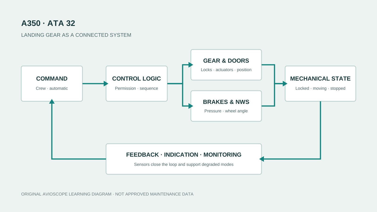
To see the same connected-system approach applied elsewhere, read the A350 Trent XWB system map and the guide to thrust-reverser control, locking and monitoring.
02 · VARIANTS
A350-900 vs A350-1000 landing gear configuration
One of the most visible differences between the two major variants is the Main Landing Gear (MLG) arrangement. Safran identifies eight main wheels and brakes plus two nose wheels on the A350-900. Airbus describes the larger A350-1000 as using a new six-wheel main landing gear.
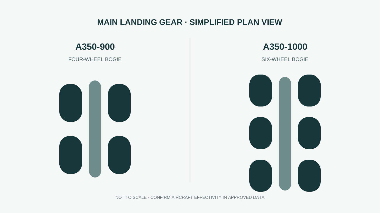
| Feature | A350-900 | A350-1000 |
|---|---|---|
| Nose landing gear | Twin wheel | Twin wheel |
| Each main bogie | Four wheels | Six wheels |
| Total main wheels | 8 | 12 |
| Learning implication | Confirm aircraft variant and effectivity before applying system theory to maintenance data. | |
The important lesson is not only wheel count. Variant differences can affect component arrangement, braking distribution, monitoring and maintenance access. Always confirm effectivity before moving from general theory to approved data.
03 · SYSTEM LOGIC
The best way to understand A350 ATA 32: follow the system logic
Use seven questions to read almost any modern aircraft system:
- Command: What input starts the request—crew control, pedal, automatic function or maintenance input?
- Control logic: Which computer decides whether the command is permitted?
- Power: Which hydraulic, electrical, stored-energy, spring or gravity source is available?
- Actuation: Which actuator, lock, valve, brake piston or steering unit moves?
- Mechanical state: What physical position should result?
- Feedback and indication: Which sensor proves the result, and what does the crew or maintenance system see?
- Degraded mode: Which independent or reduced-capability path remains after a failure?
04 · MOVEMENT
How normal landing gear extension and retraction works
A landing gear cycle is a sequence, not a single movement. In a simplified retraction sequence, the aircraft validates the relevant conditions, releases doors or locks as required, opens the necessary doors, retracts the gear, confirms its retracted position and restores the door system to the required flight configuration.
Extension has the opposite functional objective: establish access for movement, release the gear from the retracted position, extend it, establish a secure downlocked condition, then restore the doors as designed.
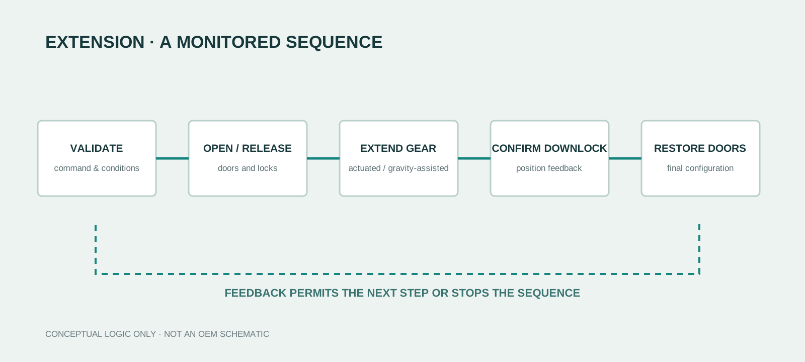
A small fault can stop or alter the sequence because the next command may depend on confirmation that the previous event occurred. Keep three states separate: the commanded state, the actual mechanical state, and the state recognised by the aircraft.
05 · MONITORING
Why landing gear monitoring is as important as movement
The aircraft must determine whether each gear and relevant door is extended, retracted, locked, unlocked, in transit or unconfirmed. Sensor information supports sequencing, cockpit indication, flight-warning logic and air/ground-dependent functions.
Weight on Wheels (WoW) information matters because multiple aircraft systems need a dependable interpretation of whether the aircraft is airborne or on the ground. A valuable troubleshooting distinction follows: is the gear physically correct but reported incorrectly, or did the mechanism fail to reach the required state? The first points toward sensing, wiring or processing; the second toward mechanical or hydraulic operation.
06 · DEGRADED MODE
What happens when normal extension is unavailable?
The A350 includes an alternate extension function intended to provide an independent route toward the landing configuration when normal extension cannot be completed. At system level, the objective is to remove dependencies that could keep the gear in the retracted state, release the required locking mechanisms, avoid hydraulic conditions that oppose movement, and let gravity and mechanical forces assist extension.
The key engineering principle is segregation. A backup is of limited value if the same failure disables both normal and alternate paths. Learn the normal energy/control path and the alternate path separately before comparing components.
07 · WHEELS & BRAKES
Understanding the A350 wheels and braking system
Braking converts aircraft kinetic energy into heat while maintaining directional control and protecting tires from excessive wheel slip. Safran identifies carbon main-wheel brakes on the A350-900 and describes its brake as a single-cavity design developed for energy absorption and cooldown performance.
Normal braking
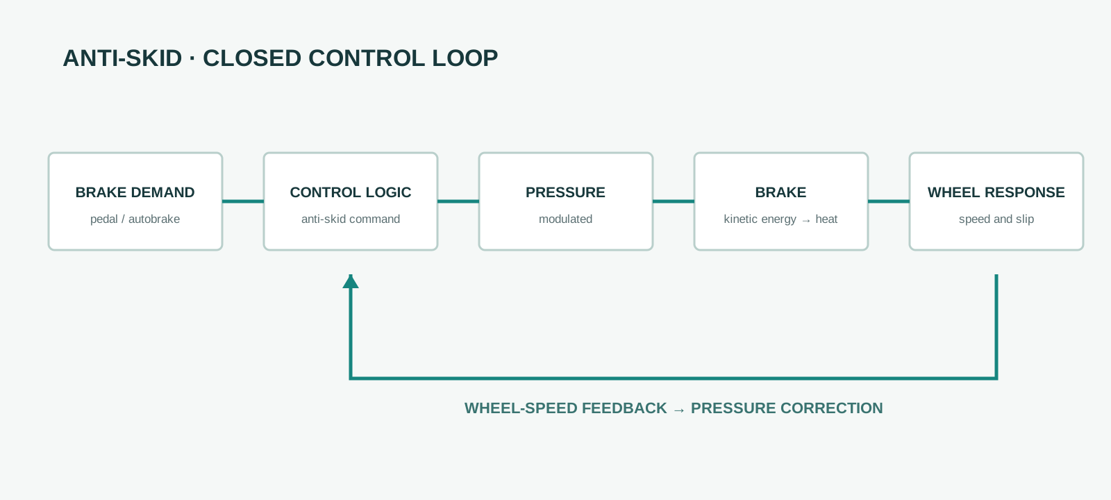
Braking demand can originate from the flight crew or an automatic braking function. Control logic interprets the request and regulates hydraulic pressure at the brakes. Pedal position and actual pressure are not necessarily identical because electronic control and anti-skid logic can modify pressure to maintain effective braking.
Alternate and emergency braking
If the normal braking path is unavailable, a separate mode can preserve braking with an alternative pressure source and control path. Further degradation may remove functions such as anti-skid or automatic braking even while pedal braking remains. Study ATA 32 as a set of operating modes, not one hydraulic schematic.
Parking braking
Parking braking holds brake application while stationary and may use stored hydraulic energy instead of continuous normal-pump operation. That stored energy is a maintenance hazard: an aircraft that appears inactive can still have pressurised accumulators.
Anti-skid and brake monitoring
Anti-skid uses wheel behaviour and aircraft motion to regulate braking and avoid excessive slip. The mental model is a closed loop:
08 · CONDITION DATA
Brake temperature and tire-pressure monitoring
Brake temperature matters because each stop turns a large amount of kinetic energy into heat. Monitoring helps identify conditions that can affect subsequent operation. Tire-pressure monitoring has a different physical purpose but follows the same information path: sensor → acquisition → processing → cockpit or maintenance indication.
Safran identifies brake-temperature and tire-pressure monitoring within modern ATA 32 landing-gear control and monitoring systems. These functions show how landing gear has evolved from mainly mechanical hardware into a networked health- and configuration-monitoring domain.
09 · STEERING
How A350 nose-wheel steering fits into ATA 32
The Nose Landing Gear supports and absorbs loads, but it also provides directional steering during ground operation. Liebherr identifies itself as supplier of the integrated nose landing gear for all A350 versions.
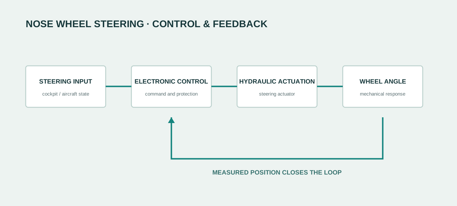
The crucial maintenance concept is feedback. A disagreement between commanded and measured wheel angle gives the system evidence of an abnormal state. Towing introduces another configuration: the nose gear must move without normal steering actuation opposing ground equipment. NWS is therefore configuration-dependent control, not merely a hydraulic actuator.
10 · TROUBLESHOOTING
A practical ATA 32 troubleshooting mindset
Do not begin with “which component should I replace?” Begin with the reported system state.
- What was the aircraft configuration when the fault occurred?
- What command was requested?
- Was the normal power source available?
- Which movement should have followed?
- Which position, pressure or speed feedback should have changed?
- What did the aircraft actually report?
- Does a redundant channel agree?
- Did the system enter a degraded mode?
- Which other systems use the same state information?
- Which current approved data applies to this aircraft and effectivity?
This framework does not replace troubleshooting documentation. It makes approved documentation easier to interpret because the engineer understands which system relationship needs verification.
11 · STUDY ERRORS
Common mistakes when studying landing gear systems
- Memorising components without the sequence. A valve or sensor name matters less than why its state must change.
- Mixing normal and alternate modes. Draw each path separately before comparing them.
- Ignoring feedback. Modern behaviour depends on what the aircraft believes happened, not only on the command.
- Treating indication as direct mechanical proof. Sensors, wiring, processing, voting and display logic sit between hardware and indication.
- Using training content as instructions. Approved maintenance data defines the applicable task.
12 · FAQ
Frequently asked questions
What is ATA 32 in aircraft maintenance?
ATA 32 is the chapter associated with Landing Gear. In system study it includes the gear and doors, extension and retraction, braking, steering and monitoring.
Are aircraft brakes part of ATA 32?
Yes. Wheel braking, control, anti-skid, parking braking and associated monitoring are normally within ATA 32.
What is the main landing gear difference between the A350-900 and A350-1000?
The A350-900 has a four-wheel bogie on each main landing gear; the A350-1000 uses a six-wheel main-gear arrangement.
Is Nose Wheel Steering part of ATA 32?
Yes. Steering is integrated with the Nose Landing Gear and belongs within ATA 32's functional architecture.
Can this article be used to perform A350 maintenance?
No. It is supplementary educational content. Use current approved data for the specific aircraft, configuration and task.
PRIMARY SOURCES
Source trail and technical boundaries
Aircraft-specific public claims in this guide were checked against manufacturer information. The diagrams are original AvioScope learning visuals and do not reproduce OEM schematics.