
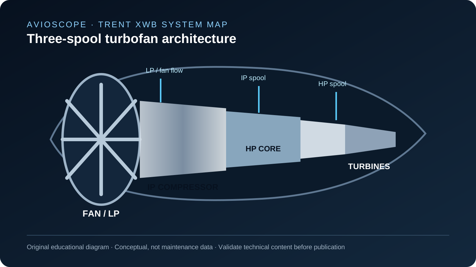
01 · Propulsion architecture
Three shafts, one purpose: convert energy into controlled thrust.
The A350-900/-1000 Trent XWB family is arranged around a fan and three concentric spools: low pressure (LP), intermediate pressure (IP) and high pressure (HP). The supplied training data identifies an LP system with the fan and six-stage turbine, an IP system with an eight-stage axial compressor and two-stage turbine, and an HP system with a six-stage compressor and single-stage turbine.
That architecture is not merely a list of modules. It is the reason control, cooling, clearances and indication must be read together: each system supports stable, efficient operation of the same core.
| System | Learning view |
|---|---|
| Fan / LP | Generates the principal mass flow and is driven by the LP turbine. |
| IP | Provides an intermediate compression stage between the LP and HP systems. |
| HP | Completes core compression and is driven by the single-stage HP turbine. |
02 · Nacelle and access
The engine is installed as a powerplant, not an isolated core.
The powerplant brings together the air inlet, fan cowl doors, thrust-reverser assembly and hot-gas exhaust. The nacelle supports inlet airflow, noise treatment and access while the structural installation carries vertical, side, torsion and thrust loads through the defined engine mounting arrangement.
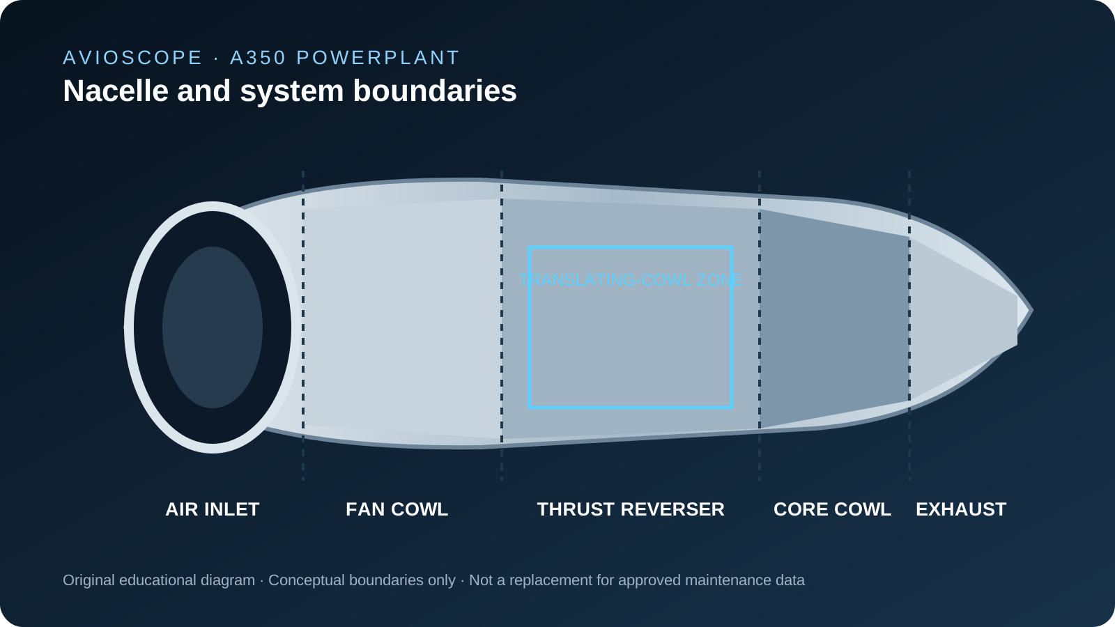
For maintenance personnel, the important mental model is therefore interface-based: access, attachment, cowl configuration and exhaust components are part of the overall system picture. Any task must still be performed only with current approved maintenance data.
03 · Control and protection
Control translates crew demand into managed engine operation.
The thrust-control and engine-protection functions sit between the aircraft command environment and the engine. The engine electronic control coordinates operating functions and provides interfaces for protection, monitoring and indication. This is why an apparent engine symptom cannot be assessed from one parameter alone: command, control logic, actuator response and reported status are connected.
A useful Level-3-style study question is: which system boundary would you check next, and why? The answer should follow the control path and approved fault-isolation information—not an assumed component replacement.
04 · Fuel, oil and air
Three systems manage energy, lubrication and the operating environment.
Fuel provides the energy path and supports engine operation from start through commanded thrust. The starting and ignition systems provide the conditions needed to initiate combustion. The oil system supplies, scavenges, cools and vents lubricant, while the engine-air system manages compressor airflow, cooling and clearance-related functions.
The supplied material describes variable inlet guide vanes and variable stator vanes as compressor-airflow controls, with bleed valves used to help prevent compressor surge or stall. It also describes oil cooling through heat-exchanger arrangements. Together, these examples illustrate a central engineering lesson: airflow, temperature, lubrication and control margins cannot be studied as independent topics.
05 · Thrust reversal in context
Thrust reversal is one controlled function within the powerplant.
The thrust-reverser assembly uses left and right translating sleeves, blocker doors and cascade vanes. The supplied training material describes it as electrically controlled and includes independent locking arrangements. Its operational integrity depends on the same disciplined control, indication, structural and maintenance interfaces that apply elsewhere in the powerplant.
Treating the reverser as a standalone topic misses the more useful engineering view: it is a nacelle-mounted system whose status must be coherent with command logic, mechanical configuration and the aircraft's protective functions.
Key takeaway
Read the Trent XWB as a system of systems.
The most durable learning outcome is not memorising a component list. It is being able to connect the propulsion architecture to its nacelle, control, thermal-management and indication interfaces, then use approved data to make the next technical decision.