
01 · ARCHITECTURE
How is the A350 hydraulic system arranged?
The source material describes two main hydraulic-power systems: Green and Yellow. Both operate at the same time, but each system is independent and there is no hydraulic fluid transfer between them.
This separation is central to the architecture. Rather than one shared hydraulic circuit, the aircraft distributes consumers across two independent pressure networks. The Green system supplies functions including parts of the flight-control system, Main Landing Gear extension/retraction, RAT retraction and a brake group. The Yellow system supplies other flight-control functions, Nose Landing Gear extension/retraction, Nose Wheel Steering, cargo-door actuation and another brake group.
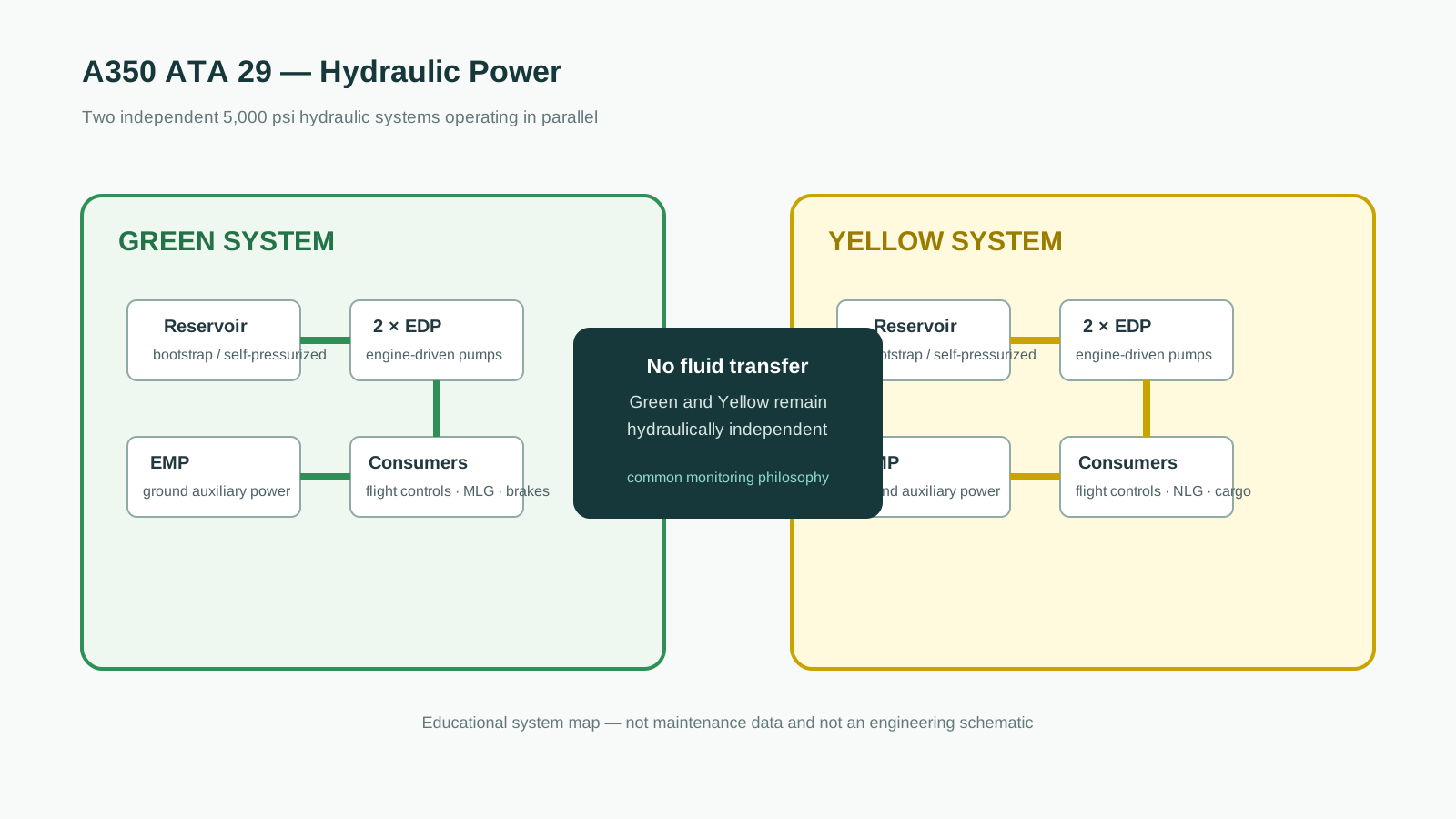
Hydraulic fuses provide local leak isolation, and the Green system uses a priority valve so the Main Landing Gear extension/retraction system receives hydraulic power only when sufficient pressure is available.
02 · POWER GENERATION
How does the A350 generate 5,000 psi hydraulic pressure?
The primary hydraulic source is the Engine Driven Pump (EDP). The source describes each EDP as a pressure-compensated, variable-displacement axial-piston pump driven by the engine Accessory Gear Box. There are two EDPs on each engine—one for Green and one for Yellow—so each hydraulic system has a pump on both engines.
In normal engine operation the EDPs run continuously and pressurize their respective hydraulic systems to approximately 5,000 psi. Hydraulic fluid leaves the reservoir through the suction line and Fire ShutOff Valve (FSOV), passes through the EDP, then flows through the high-pressure manifold and filter before reaching the system consumers.
The aircraft also has one Electric Motor Pump (EMP) per hydraulic system. Each EMP uses a 230 VAC, 400 Hz motor and is intended for ground operation when the engines are not running. The EMP can support maintenance tasks, brake-accumulator refill and—on the Yellow system—cargo-door operation.
A ground hydraulic cart can also pressurize either system through Ground Service Panel connections. The Yellow Ground Service Panel additionally includes an auxiliary hydraulic pump for cargo-door operation.
03 · RESERVOIRS
Why are the A350 hydraulic reservoirs self-pressurized?
Each hydraulic system has its own reservoir. The source describes them as bootstrap-type self-pressurized reservoirs operating at about 70 psi differential pressure. Reservoir pressurization helps prevent pump cavitation, improves pump inlet conditions and reduces the risk of air entering the system through external seals.
The Green reservoir is located on the inner right side of the rear belly fairing, while the Yellow reservoir is installed in the Main Landing Gear bay. The reservoirs include level, pressure and temperature sensing, relief protection and depressurization provisions.
Each system also has a metal-bellow accumulator pre-charged with helium. The accumulator absorbs pump pulsations and pressure surges, supplements transient flow demand and works with a pressure-maintaining valve to help keep the reservoir pressurized after shutdown.
04 · DISTRIBUTION
How does hydraulic power reach aircraft consumers?
After pressurization, fluid is distributed through high-pressure manifolds, system manifolds and dedicated supply lines. Return fluid flows through the low-pressure return network and filter before returning to the reservoir.
The system manifold is especially important during ground operation. It receives fluid from the EDPs and can also receive pressure from the EMP or Ground Service Panel. An isolation valve determines whether ground-generated pressure remains restricted to auxiliary users or is connected to the wider hydraulic system.
The system includes non-bypass high-pressure filtration, bypass-capable return filtration, check valves and hydraulic fuses. The source notes that hydraulic fuses close when unusually high leakage flow is detected, protecting the rest of the hydraulic system from losing fluid through a major downstream leak.
05 · TEMPERATURE CONTROL
How is hydraulic fluid temperature controlled?
The ATA 29 source describes active thermal management using both heating and cooling functions. Temperature-control valves can route high-pressure fluid to the low-pressure side when the fluid is cold, increasing hydraulic-fluid temperature under suitable pressure conditions.
Cooling is provided by Hydraulic Heat Exchangers (HHXs) installed in the wing fuel tanks. They cool the EDP case-drain flow using fuel as the heat sink. A thermal bypass valve controls whether case-drain flow bypasses or passes through the heat exchanger as temperature changes.
This architecture matters because hydraulic-fluid temperature affects viscosity, pressure losses, component durability and fluid life. Maintenance interpretation should therefore consider reservoir temperature, case-drain temperature and the system's cooling path together rather than as isolated indications.
06 · MONITORING & INDICATION
What monitors the A350 hydraulic system?
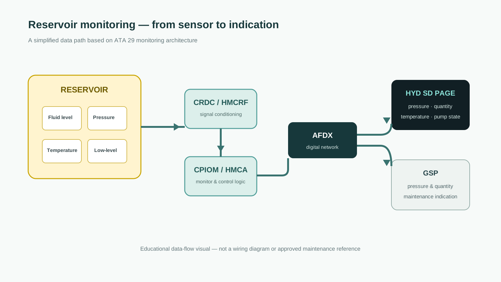
The source describes a Hydraulic Monitoring and Control (HMC) function divided into the Hydraulic Monitoring and Control Application (HMCA) and Hydraulic Monitoring and Control Remote Function (HMCRF). HMCA functions are hosted in CPIOMs, while HMCRF functions are hosted in CRDCs.
Together they monitor items including engine-pump pressure and clutch position, electric-pump status, system pressure, reservoir pressure, fluid quantity, fluid temperature, filter clogging, temperature-control valves and cockpit pushbutton states. They also support control functions such as EDP depressurization, EMP control, FSOV control, isolation-valve control and BITE tests.
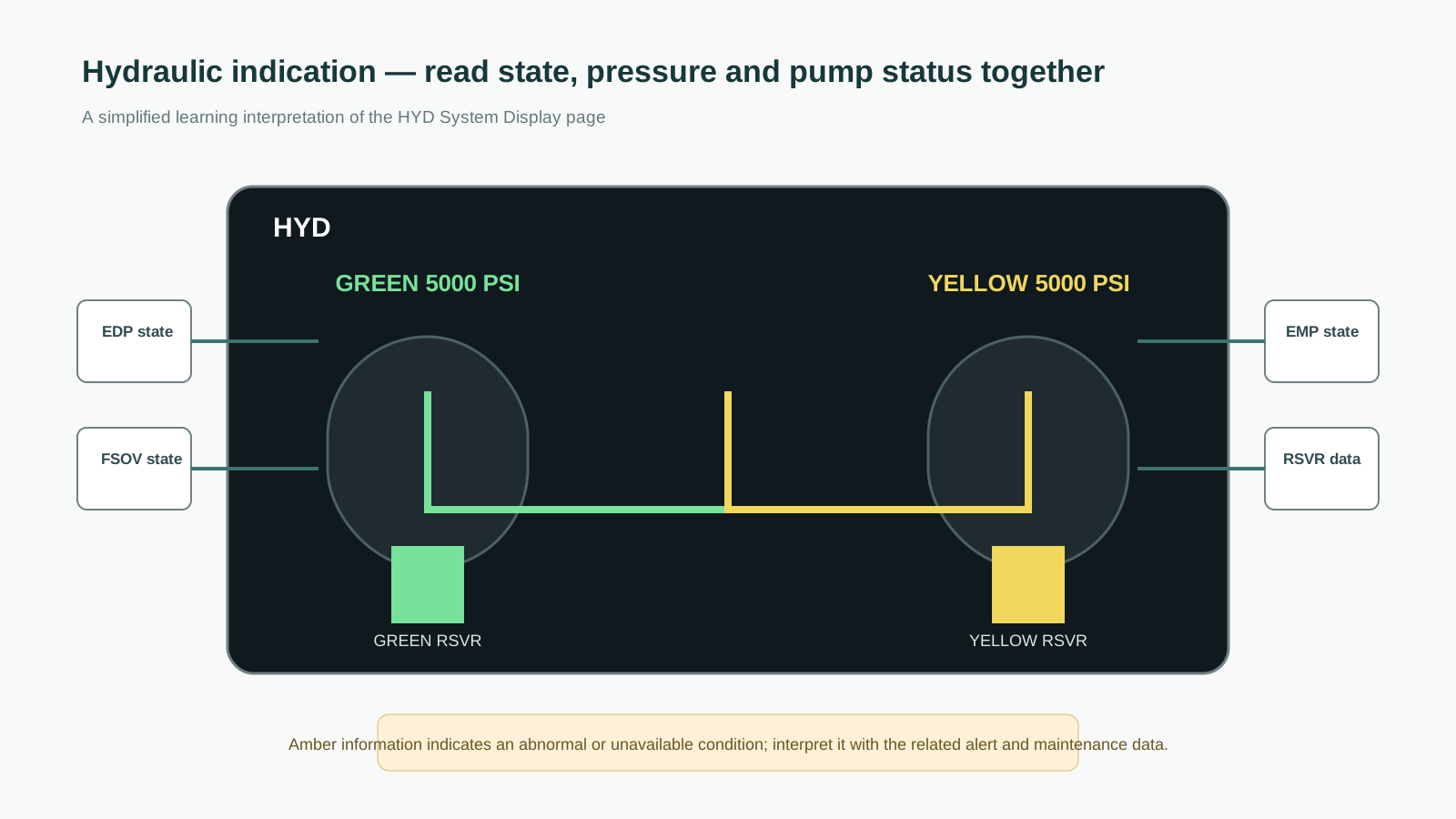
The hydraulic System Display page presents the system state to the crew. The source describes normal pressure and operating components in green, while low pressure, pump faults, closed valves and invalid data can be shown in amber depending on the condition.
07 · GROUND SERVICE
How is the hydraulic system used during maintenance?
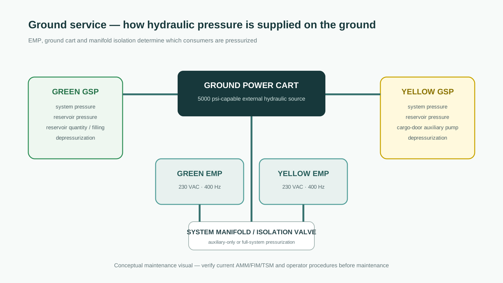
Ground maintenance uses dedicated Green and Yellow Ground Service Panels. The Green panel provides functions for system pressurization, Green reservoir pressure, both-reservoir quantity monitoring, reservoir filling and Green reservoir depressurization. The Yellow panel provides Yellow system pressure and reservoir pressure monitoring, cargo-door auxiliary power and Yellow reservoir depressurization.
When an EMP is started for a specific auxiliary demand, the system manifold isolation valve can remain closed so only the required auxiliary function is supplied. When the EMP is manually selected from the cockpit for maintenance, or when the manifold isolation switch is selected during ground-cart operation, the isolation valve can open and allow the full hydraulic system to be pressurized.
08 · MAINTENANCE PERSPECTIVE
A useful troubleshooting mindset for ATA 29
For maintenance learning, it is helpful to follow the hydraulic system as a chain rather than jumping directly to a component:
- Source: Which pressure source should be active—EDP, EMP, ground cart or auxiliary pump?
- Supply path: Is the FSOV open and is reservoir pressure sufficient?
- Pressure generation: Is the pump actually generating pressure, and is the high-pressure manifold sensing it?
- Distribution: Is the system manifold or isolation valve routing pressure to the intended users?
- Return path: Is return flow unobstructed and are filters or bypass indications normal?
- Thermal state: Are reservoir and case-drain temperatures within the expected range?
- Monitoring: Do HMCA/HMCRF, ECAM and Ground Service Panel indications agree with the physical condition?
This approach does not replace FIM or TSM fault isolation. It simply helps build the system model needed to use approved troubleshooting data effectively.
09 · FAQ
Frequently asked questions
How many hydraulic systems does the Airbus A350 have?
The source describes two main hydraulic-power systems: Green and Yellow. They operate simultaneously and independently, with no hydraulic fluid transfer between them.
What is the normal hydraulic pressure on the A350?
The Engine Driven Pumps and ground electric pumps pressurize the systems to approximately 5,000 psi.
What is the difference between an EDP and an EMP?
An EDP is mechanically driven by the engine Accessory Gear Box and is the primary in-flight hydraulic source. An EMP is electrically driven and is mainly used on the ground for maintenance and auxiliary demands.
What does the HMCA do?
The HMCA monitors and controls the hydraulic system. It processes system-state information and supports functions including pump control, valve control, monitoring and BITE.
Can the Green and Yellow hydraulic systems transfer fluid between each other?
No. The source explicitly states that there is no hydraulic fluid flow between the two systems.
CONCLUSION
The A350 hydraulic system is best understood as two independent power networks
ATA 29 becomes easier to understand when the system is followed from reservoir to pump, manifold, consumer, return path and monitoring logic. The Green and Yellow systems share a common design philosophy, but they remain hydraulically independent and distribute aircraft functions between them to provide system resilience.
For a maintenance engineer, the most useful mental model is not simply “hydraulic pressure available or not available.” The important question is which source should be active, which path should be open, what the system is physically doing and whether the monitoring architecture confirms that state.